Field Report: High-Penetration Robotic Integration for Tool Steel Applications
Project Location: São Bernardo do Campo, São Paulo, Brazil
This report details the operational deployment and technical validation of a high-performance MIG/MAG Welding Robot at a Tier-1 automotive tooling facility in the industrial belt of Sao Paulo. The objective was to transition from manual GTAW (TIG) processes to an automated deep-penetration system capable of handling complex Tool Steel welding requirements. In the context of the Brazilian manufacturing sector, where downtime is prohibitively expensive and skilled manual welders for high-alloy materials are increasingly scarce, the integration of automated Arc Welding Solutions has become a strategic necessity rather than a luxury.
The MIG/MAG Welding Robot: Hardware Configuration and Shop Floor Integration
The core of the installation is a 6-axis industrial MIG/MAG Welding Robot equipped with a specialized hollow-wrist design for high-duty cycle torch leads. Unlike standard structural steel setups, the Sao Paulo facility required a system that could manage the high torque and thermal loads associated with Tool Steel welding. We utilized a water-cooled torch assembly capable of sustained 500A output, as the penetration requirements for the die-repair section of the plant necessitated deep-groove fusion.
One of the primary lessons learned during the first week of installation involved the local power infrastructure. In the older industrial zones of Sao Paulo, voltage fluctuations are common during peak shift hours (between 10:00 AM and 2:00 PM). To ensure the MIG/MAG Welding Robot maintained arc stability, we had to implement a dedicated power conditioning unit. Without this, the robot’s controller would lose synchronization with the wire feeder’s encoder, leading to “bird-nesting” and erratic penetration depths—catastrophic when dealing with expensive tool steel billets.
Mechanical Repeatability and Path Planning
The robot was programmed using an offline programming (OLP) suite, which allowed us to simulate the complex geometries of the tool dies. However, real-world application in the Sao Paulo workshop revealed discrepancies in workpiece positioning. We integrated a laser-touch sensing system to allow the MIG/MAG Welding Robot to “locate” the tool steel workpiece before striking the arc. This adjustment ensures that the deep penetration pass is centered exactly in the V-groove, minimizing the risk of sidewall lack-of-fusion, which is a common failure point in automated Tool Steel welding.
Advanced Arc Welding Solutions: Synergy and Waveform Control
The term “Arc Welding Solutions” refers to more than just a power source; it encompasses the digital communication between the robot controller and the inverter. In Sao Paulo, we deployed a high-speed digital interface that allows the MIG/MAG Welding Robot to adjust parameters in real-time based on the feedback from the arc. This synergy is critical when the material chemistry of the tool steel varies slightly between batches.
Waveform Modulation for Deep Penetration
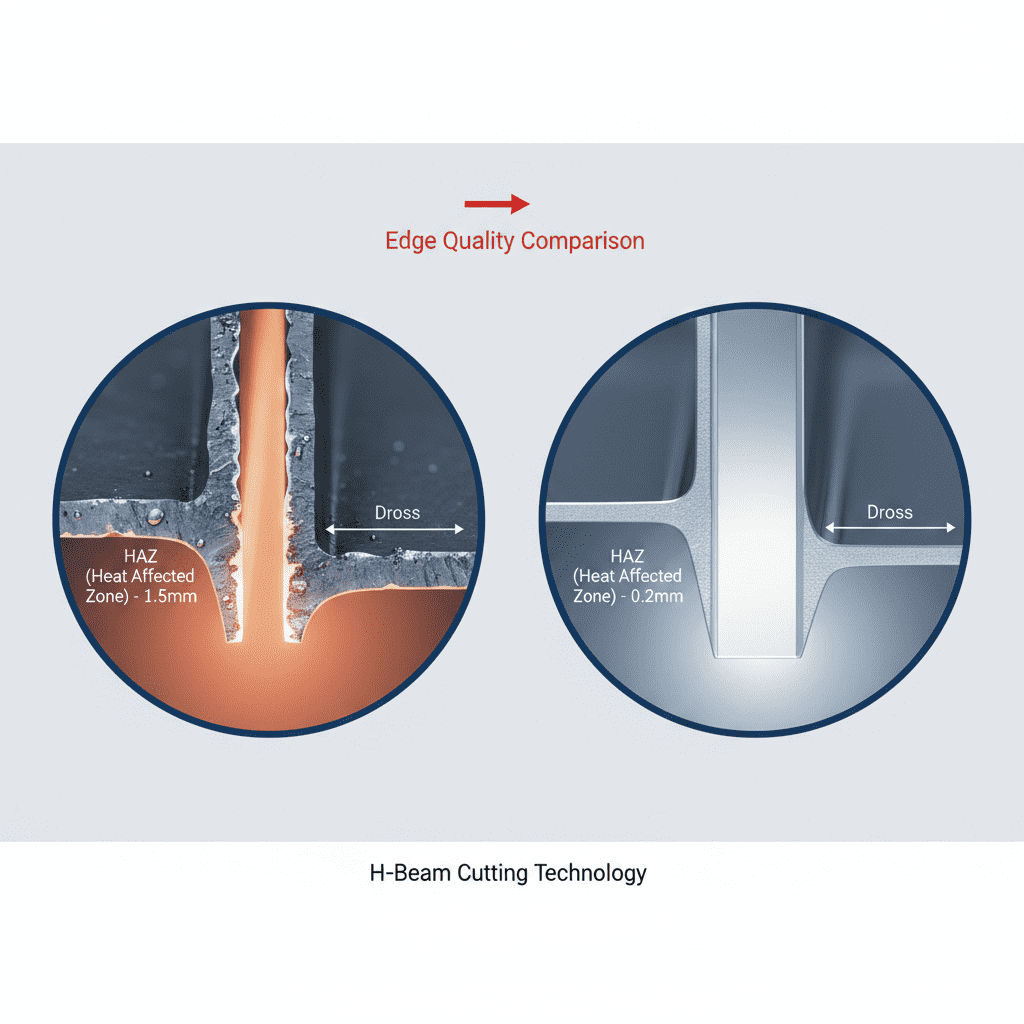
Standard spray transfer is often too turbulent for high-precision Tool Steel welding, leading to excessive spatter and a wide heat-affected zone (HAZ). To combat this, our Arc Welding Solutions included a modified pulsed-spray waveform. This specific waveform uses a high-frequency peak current to pinch off the molten droplet, followed by a controlled background current that maintains the puddle without adding excessive heat. This “deep penetration” mode allows for a narrower, deeper weld bead, which is essential for structural integrity in tool dies subjected to high cyclic loading.
Shielding Gas Dynamics in High Humidity
A significant environmental challenge in Sao Paulo is the high relative humidity, which often exceeds 80%. Moisture in the air can lead to hydrogen-induced cracking, especially in tool steels. Our Arc Welding Solutions included a dual-stage gas filtration and drying system. We transitioned the plant from a standard 80/20 Argon-CO2 mix to a triple-mix (Argon/CO2/O2) to improve arc stiffness and surface tension. The oxygen addition (approx. 2%) helped stabilize the arc at high travel speeds, allowing the MIG/MAG Welding Robot to maintain a consistent penetration profile even when the gas lines were subject to the local humidity spikes.
Technical Challenges in Tool Steel Welding
Tool Steel welding is notoriously difficult due to the high carbon and alloy content (Chromium, Molybdenum, Vanadium). These elements increase hardenability, making the material prone to cracking in the HAZ if the cooling rate is not strictly controlled. The transition from manual to robotic welding required a complete rethink of the thermal management strategy.
Managing the Heat-Affected Zone (HAZ)
With the MIG/MAG Welding Robot, we can achieve much higher travel speeds than manual operators. This higher speed reduces the total heat input per linear inch, which sounds beneficial but can actually lead to faster cooling rates and the formation of brittle martensite. To mitigate this, we integrated an induction pre-heating system that works in tandem with the robot’s pathing. The Arc Welding Solutions software was programmed to monitor the interpass temperature via an infrared pyrometer. If the tool steel dropped below 250°C, the robot would pause or adjust its speed to maintain the required thermal gradient.
Wire Selection and Metallurgy
For this specific application in Brazil, we utilized a metal-cored wire specifically designed for Tool Steel welding (H13 and D2 equivalents). Metal-cored wires provide a broader arc cone than solid wires, which helps in wetting the sidewalls, but when combined with the high current density of the MIG/MAG Welding Robot, they provide the necessary “jet” action for deep penetration. The metallurgical match between the filler and the base tool steel was validated through cross-sectional macro-etching in the onsite lab, showing a seamless transition and minimal porosity.
Lessons Learned and Field Observations
The Sao Paulo project yielded several critical insights for future robotic deployments in the South American market:
1. Grounding Integrity
Many “ghost in the machine” issues with the MIG/MAG Welding Robot—such as erratic arc starts and sensor interference—were traced back to poor high-frequency grounding in the facility. In Brazil, older factory slabs often lack a dedicated grounding grid. We had to install a copper grounding spike specifically for the welding cell to isolate the Arc Welding Solutions from the rest of the factory’s electrical noise.
2. Consumable Life in Tropical Climates
We observed that contact tips were wearing out 30% faster than in our European trials. Investigation revealed that the high ambient temperature in Sao Paulo was affecting the cooling efficiency of the torch. We upgraded the chiller unit capacity by 50%, which immediately stabilized the contact tip life and improved the wire feed consistency of the MIG/MAG Welding Robot.
3. The “Human-Robot” Synergy
While the goal was automation, the success of the Arc Welding Solutions depended on the local operators’ understanding of “Tool Steel welding” physics. We conducted a two-week intensive workshop focusing on weld pool geometry and the importance of wire stick-out (CTWD). Even with a robot, if the operator sets the workpiece offset incorrectly by 2mm, the deep penetration benefits are lost, and the risk of tool failure increases.
Conclusion: The Path Forward
The implementation of the MIG/MAG Welding Robot at the Sao Paulo facility has resulted in a 45% increase in throughput for the tool repair department. More importantly, the consistency provided by our integrated Arc Welding Solutions has reduced the rework rate on Tool Steel welding from 12% to under 1.5%. The deep penetration capabilities of the system have proven that high-speed robotic welding is not only possible for high-alloy materials but superior to manual methods when the environmental and metallurgical variables are strictly controlled.
Future phases of this project will involve the deployment of “Twin-Wire” robotic systems to further increase deposition rates, provided we can maintain the delicate balance of the heat-affected zone required for these sensitive tool steels. The Sao Paulo site now serves as a regional benchmark for automated Arc Welding Solutions in the heavy tool and die industry.
-


LT240S tube laser cutting machine
-
LT120S tube laser cutting machine
-
Sale

Tank Fillet Welding Machine
Original price was: $1,000.00.$900.00Current price is: $900.00. -
Sale

MAK100 tube laser cutting machine
Original price was: $5,500.00.$5,000.00Current price is: $5,000.00. -

portable plasma air cutting machine
$1,200.00 -

2in1 fiber laser cutting machine
-

Air cooling Laser welding machine
-

HF h beam laser cutting machine
-

LT240 laser cutting machine
-

Laser welding machine
-


Cobot Welding Station
-

Gantry welding robot solution
-

Tracked Wheeled AGV Welding robot
-

LFH6020 Fiber laser cutting machine
-
LFP6020
-

robotic welidng machine
Advanced Fiber Laser Tube Processing Technology
Our CNC Fiber Laser Tube Cutting systems revolutionize metal fabrication by integrating high-precision cutting, punching, and profiling into a single automated workflow. Designed for versatility, this technology handles a wide array of profiles including Round, Square, Rectangular, and Oval tubes, as well as complex L-shaped and U-shaped channels.
- Precision Punching: High-speed hole punching with micron-level accuracy, eliminating the need for mechanical drilling or die-stamping.
- Complex Profiling: Advanced 3D pathing allows for intricate interlocking joints and specialized notch cuts, ideal for structural frames.
- High Material Efficiency: Intelligent nesting software minimizes scrap, reducing raw material costs across large production runs.
- Clean Finish: Delivers oxide-free, burr-free edges that require zero secondary grinding before welding.

Seamlessly processing multiple profiles with consistent precision.
Global Delivery & Logistics



From our high-tech manufacturing facility directly to your global site. PCL WeldCut ensures secure packaging, professional handling, and reliable international logistics to safeguard your equipment throughout the entire journey.