Engineering Review: Air-cooled Robotic Arm Welder – Illinois, USA
In this article
- Field Engineering Report #4492-IL: Robotic Integration for Aluminum Fabrications
- 1.0 Executive Summary
- 2.0 System Configuration and Environment
- 3.0 Synergy: Robotic Arm Welder and Industrial Automation
- 4.0 Technical Deep-Dive: Aluminum Alloy Welding Challenges
- 5.0 Performance Analysis and Site Observations
- 6.0 Lessons Learned: Field Engineering Perspective
- 7.0 Optimization Recommendations
- 8.0 Conclusion
Field Engineering Report #4492-IL: Robotic Integration for Aluminum Fabrications
1.0 Executive Summary
This report details the onsite commissioning and optimization of a 6-axis air-cooled Robotic Arm Welder system at a mid-sized fabrication facility in Aurora, Illinois. The primary objective was the transition from manual GTAW (Gas Tungsten Arc Welding) to a high-throughput Industrial Automation solution specifically for Aluminum Alloy welding (primarily 5052 and 6061 grades).
The transition to Industrial Automation in the Illinois manufacturing sector is often driven by the scarcity of specialized labor capable of handling the high thermal conductivity and narrow melting ranges of aluminum. This installation demonstrates that while air-cooled systems offer lower maintenance overhead, they require stringent parameter management to avoid torch overheat and wire-feed inconsistencies common in the humid Midwestern summer months.
2.0 System Configuration and Environment
2.1 Hardware Specification
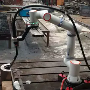
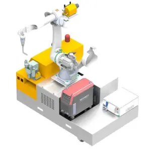
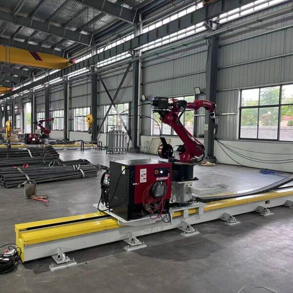
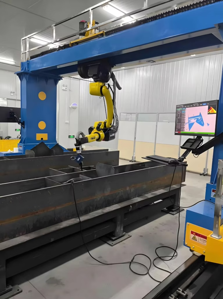
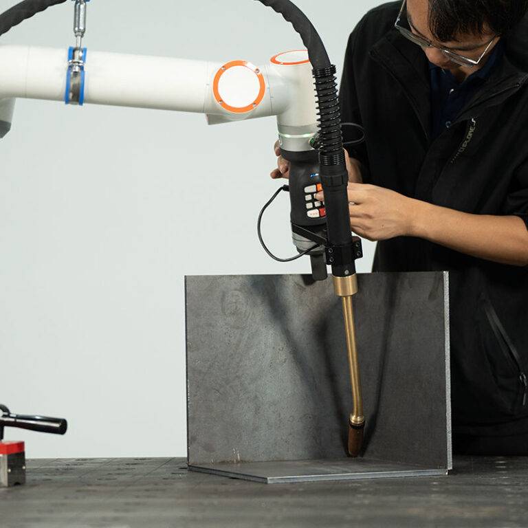
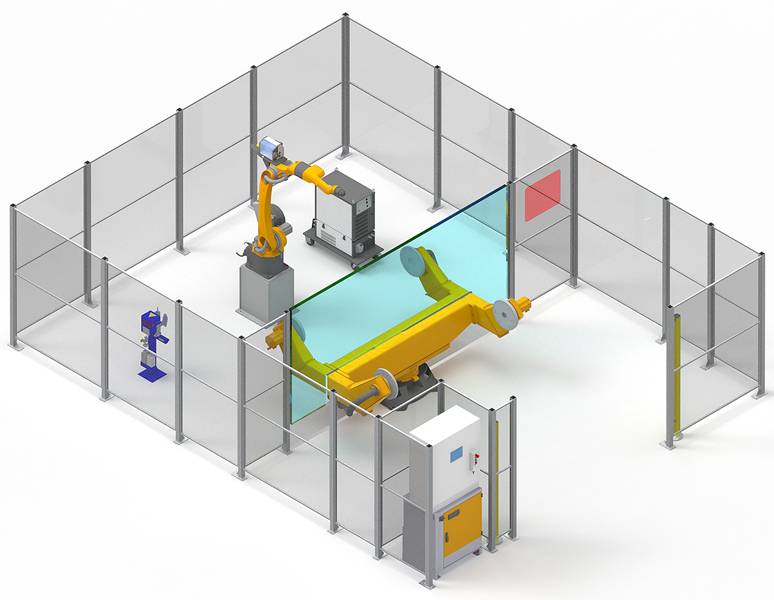
The cell utilizes a high-speed Robotic Arm Welder equipped with a specialized air-cooled push-pull torch assembly. Unlike water-cooled variants, this system was selected to minimize peripheral equipment footprint and reduce the risk of coolant leaks contaminating the sensitive Aluminum Alloy welding environment. The arm is integrated with a 400A pulse-capable power source designed for high-frequency communication with the robot controller.
2.2 The Illinois Operational Context
Working in the Illinois industrial corridor presents specific environmental challenges. During this site visit, the facility ambient temperature reached 92°F with 70% humidity. For an air-cooled Robotic Arm Welder, these conditions are the “worst-case scenario” for duty cycle ratings. We observed that the internal thermistors in the torch head reached 85% of their thermal limit during a continuous 15-minute cycle of 5052-H32 bracket fabrication. This required a recalibration of the inter-pass cooling delays within the Industrial Automation logic.
3.0 Synergy: Robotic Arm Welder and Industrial Automation
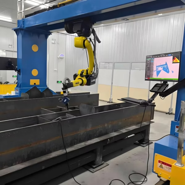
The true value of Industrial Automation is not merely the speed of the arm, but the deterministic nature of the process. When we marry a Robotic Arm Welder to a centralized PLC (Programmable Logic Controller), we eliminate the “human variable” in travel speed, which is the single most critical factor in managing the Heat Affected Zone (HAZ) in Aluminum Alloy welding.
3.1 Data-Driven Parameter Control
In this Illinois workshop, we implemented a “Smart Start” routine. The Industrial Automation system polls the ambient temperature and adjusts the pre-flow of Argon shielding gas accordingly. Because aluminum acts as a massive heat sink, the Robotic Arm Welder was programmed with a ramp-down crater fill routine to prevent the common “star crack” defect associated with rapid cooling in 6000-series alloys. This synergy allows for a level of consistency that manual operators, regardless of skill, cannot maintain over an 8-hour shift.
4.0 Technical Deep-Dive: Aluminum Alloy Welding Challenges
4.1 Oxide Layer Management
Aluminum’s affinity for oxygen creates a tenacious oxide layer (Al2O3) that melts at nearly three times the temperature of the base metal. Our Industrial Automation setup utilized a pulse-on-pulse wave profile. The Robotic Arm Welder was programmed to maintain a specific torch angle (15-degree push) to ensure the cathodic cleaning action of the arc effectively “scoured” the oxide layer ahead of the weld pool.
4.2 Wire Feed Consistency
One of the “lessons learned” during this deployment involved the soft nature of the ER4043 filler wire. In a Robotic Arm Welder setup, any resistance in the liner causes “bird-nesting.” Even with a push-pull system, we found that the standard nylon liners were failing prematurely due to micro-shavings from the wire. We swapped these for graphite-impregnated liners, which significantly reduced the torque load on the Industrial Automation drive motors.
5.0 Performance Analysis and Site Observations
5.1 Throughput vs. Thermal Limits
The facility aimed for a 30% increase in throughput. However, the air-cooled torch on the Robotic Arm Welder reached its thermal threshold at the 18-unit mark during continuous operation. In Industrial Automation, you are only as fast as your weakest cooling component. We adjusted the sequence to include a “torch cleaning” cycle every 5 units, which provided a 45-second air-purge to lower the internal nozzle temperature.
5.2 Weld Integrity in 6061-T6 Applications
6061-T6 is notoriously prone to liquation cracking. By utilizing the Robotic Arm Welder, we maintained a travel speed of 24 inches per minute (IPM) with a 180A pulse. This speed-to-heat ratio is difficult to maintain manually without wandering. The Industrial Automation sensors monitored the voltage feedback in real-time, adjusting the arc length to compensate for the slight thermal warping of the aluminum plates during the run.
6.0 Lessons Learned: Field Engineering Perspective
Working the Illinois manufacturing circuit for twenty years, I’ve seen automation fail not because of the robot, but because of the prep. Aluminum Alloy welding is 90% preparation and 10% execution.
6.1 Grounding Issues
One critical lesson from this site: The robotic pedestal was sharing a common ground with a CNC plasma table. This induced high-frequency noise into the Robotic Arm Welder‘s encoder cables, causing “jitter” during circular interpolations. We isolated the welding ground and installed a dedicated copper earth-ground for the Industrial Automation rack. The arc stability improved immediately.
6.2 Shielding Gas Contamination
The shop’s bulk gas system had a slight leak at a manifold. While Industrial Automation handles the movement, it cannot “see” a contaminated weld pool like a human can—until the post-weld inspection. We integrated a digital flow meter into the Robotic Arm Welder‘s I/O, which triggers an E-stop if the gas flow drops below 35 CFH. This prevented the scrap of twenty 6061 alloy frames.
7.0 Optimization Recommendations
For future Industrial Automation rollouts in the Illinois region, especially involving air-cooled systems, I recommend the following:
- Active Torch Cooling: Even if the torch is air-cooled, the mounting bracket on the Robotic Arm Welder should be heat-sinked to the robot’s casting to dissipate secondary heat.
- Wire Lubrication: Use treated wipes at the wire entry point. In Aluminum Alloy welding, reducing friction in the feed path is the difference between 99% uptime and constant downtime.
- Localized Dehumidification: Given the Illinois climate, a localized dehumidifier near the wire spool cabinet is essential to prevent moisture absorption into the aluminum wire, which is a primary cause of hydrogen porosity.
8.0 Conclusion
The integration of the Robotic Arm Welder at the Aurora facility has successfully demonstrated that Industrial Automation is viable for complex Aluminum Alloy welding, provided the thermal limitations of air-cooled hardware are respected. The synergy between the high-precision arm and the pulse-power source has reduced rework rates from 12% (manual) to under 0.5% (automated).
As we move forward, the focus will shift to predictive maintenance, using the data logged by the Industrial Automation system to identify tip-wear patterns and liner degradation before they impact the weld quality. The “Illinois grit” of this workshop, combined with high-tier robotic precision, sets a new standard for regional aluminum fabrication.
Senior Field Engineer: J. R. Sterling
Location: Aurora, Illinois, USA
Status: Commissioning Complete / Handover in Progress