Field Report: Deployment of 6-Axis Collaborative Welder Systems in Quebec Industrial Corridors
1. Project Overview and Environmental Context
This report details the technical deployment and performance validation of air-cooled 6-Axis Collaborative Welder units across three manufacturing facilities in the Greater Montreal and Saguenay–Lac-Saint-Jean regions. The objective was to transition high-mix, low-volume production lines from manual stations to Automated Welding to address the acute skilled labor shortage currently impacting the Quebec manufacturing sector.
The environmental factors in Quebec workshops—specifically the significant fluctuations in ambient humidity and temperature between seasons—necessitated a rigorous look at how air-cooled systems handle Aluminum Alloy welding. Unlike water-cooled variants, the air-cooled 6-axis systems offer a simplified footprint, which is critical for the cramped shop floors typical of older industrial zones in Lachine and Saint-Laurent.
2. Technical Configuration: The 6-Axis Collaborative Welder
The core of the installation is a high-degree-of-freedom (6-axis) collaborative arm integrated with a digital power source. The choice of a 6-Axis Collaborative Welder over traditional industrial robotics was driven by the need for “hand-guiding” lead-through programming. In a province where the welding workforce is aging, the ability for a veteran welder to physically move the robot arm to define a path—rather than coding coordinates—is the difference between project adoption and shelfware.
4.1 Payload and Reach Dynamics
We utilized a 10kg payload arm to account for the torch, wire feeder, and cable management. The 6th axis is particularly vital for maintaining the work angle (10-15 degrees) and travel angle during complex circular interpolations on 6061-T6 aluminum tubing. In Automated Welding, the precision of the 6th axis ensures that the arc remains centered in the joint, compensating for minor fit-up inconsistencies that occur during manual tacking.
3. Synergy: Automated Welding and Collaborative Flexibility
The synergy between the 6-Axis Collaborative Welder and Automated Welding protocols lies in the transition from “operator” to “process technician.” In the Quebec context, we found that by automating the torch oscillation and travel speed, we could achieve a 40% increase in arc-on time.
The automation component isn’t just about the robot moving; it’s about the digital communication between the robot controller and the power source. We utilized a “Job Mode” configuration where the 6-axis arm triggers specific pulse-on-pulse parameters depending on its position in 3D space. This is critical when transitioning from a flat position to a vertical-up position in a single continuous weldment.
4. The Aluminum Alloy Welding Challenge
Aluminum Alloy welding in a collaborative environment presents unique hurdles, specifically regarding heat dissipation and wire feed consistency. Aluminum’s high thermal conductivity means the heat-affected zone (HAZ) expands rapidly.
4.1 Porosity and Oxide Management
In our Saguenay site, we dealt heavily with 5xxx and 6xxx series alloys. The primary lesson learned: air-cooled torches require a higher flow rate of shielding gas (typically 100% Argon or an Argon-Helium mix) to compensate for the lack of internal liquid cooling. However, in Quebec winters, the shop air is dry, which can lead to static buildup in the wire liners, causing “bird-nesting” at the drive rolls. We solved this by switching to specialized PTFE (Teflon) liners and U-groove rollers specifically calibrated for the softer aluminum wire.
4.2 Heat Saturation in Air-Cooled Torches
While air-cooled systems are lighter and more maneuverable for a 6-axis arm, they have a lower duty cycle. During Automated Welding of 1/4″ aluminum plates, we monitored the torch neck temperature. We found that after 10 minutes of continuous arc-on time, the contact tip expansion began to cause micro-arcing inside the tip. The fix was a programmed “cooling path” where the robot moves to a cleaning station every three cycles, allowing the air-cooled heat sinks to dissipate energy.
5. Implementation Notes: Quebec Shop Floor Integration
Integration in Quebec requires compliance with CNESST safety standards. Because these are collaborative welders, we initially hoped to run them without fencing. However, the “collaborative” nature refers to the robot’s motion, not the welding arc. The UV radiation and fumes from Aluminum Alloy welding still necessitate high-grade flash shielding and localized extraction (fume arms).
5.1 Programming for High-Mix Production
We utilized the 6-axis flexibility to handle four different part numbers on a single table. The “synergy” here is found in the software. By using the robot’s I/O to sense the fixture type, the Automated Welding program automatically adjusts the wire feed speed and voltage for different aluminum gauges. This reduces the changeover time from 30 minutes to nearly zero.
6. Lessons Learned and Engineering Recommendations
After six months of field operation, several critical technical insights have emerged for senior engineers looking to deploy similar systems:
- Wire Delivery: For Aluminum Alloy welding, the distance between the wire spool and the 6-axis head must be minimized. We observed a 15% increase in arc instability for every meter of conduit beyond 3 meters. Use a top-mounted feeder whenever the 6-axis payload allows.
- Contact Tip Consumables: Standard copper tips fail prematurely in Automated Welding of aluminum. Switching to Chrome-Zirconium-Copper (CuCrZr) tips provided a 3x lifespan increase, which is vital for maintaining the “lights-out” capability of the system.
- Gas Pre-Flow: Quebec’s humid summers lead to condensation in gas lines overnight. We implemented a “First Weld of the Day” macro that purges the lines for 30 seconds to prevent initial porosity in the first production part.
- Joint Tracking: While the 6-axis arm is precise, aluminum extrusions often have “twist.” For true Automated Welding success, integrating a laser touch-sense or “Through-Arc Seam Tracking” (TAST) is recommended, although TAST is difficult on thin-gauge aluminum due to the low amperage.
7. Conclusion: The Path Forward for Quebec SMBs
The deployment of the 6-Axis Collaborative Welder has proven that Automated Welding is no longer reserved for Tier-1 automotive plants with massive floor space. For aluminum fabricators in Quebec, the air-cooled cobot represents a middle ground: it offers the precision needed for Aluminum Alloy welding without the infrastructure overhead of a water-cooled, caged industrial cell.
The success of these systems hinges not on the robot itself, but on the welding engineer’s ability to translate manual “feel” into digital parameters. As we move forward, the focus must remain on perfecting the wire-feed path and ensuring that the air-cooled torch duty cycles are respected through intelligent path planning. The result is a consistent, high-quality bead profile that meets CWB (Canadian Welding Bureau) standards while significantly reducing the physical strain on the human workforce.
Report Prepared By:
Senior Welding Engineer
Field Operations Division – Quebec
-


Cantilever Welding Robot solution
-


GF laser cutting machine
-

P3015 plasma cutting machine
-

LFP3015 Fiber Laser Cutter
-

pipe plasma cutting machine
-
LFH 4020 Fiber Laser Cutting Machine
-
LFP4020
-

gantry plasma air cutting machine
-

3D robot cutting machine
-

8 axis plasma cutting machine
-

5 axis plasma cutting machine
-

LT360 tube laser cutting machine
-

robot welding workstation
-

SF6060 fiber laser cutting machine
Advanced Fiber Laser Tube Processing Technology
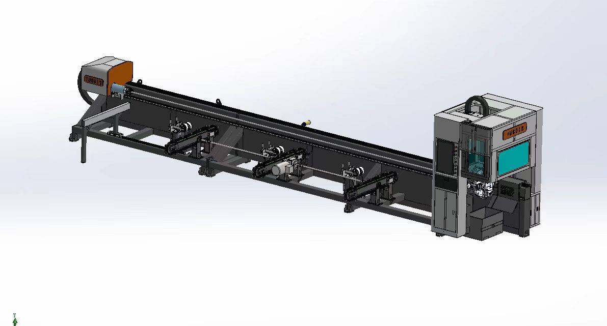
Our CNC Fiber Laser Tube Cutting systems revolutionize metal fabrication by integrating high-precision cutting, punching, and profiling into a single automated workflow. Designed for versatility, this technology handles a wide array of profiles including Round, Square, Rectangular, and Oval tubes, as well as complex L-shaped and U-shaped channels.
- Precision Punching: High-speed hole punching with micron-level accuracy, eliminating the need for mechanical drilling or die-stamping.
- Complex Profiling: Advanced 3D pathing allows for intricate interlocking joints and specialized notch cuts, ideal for structural frames.
- High Material Efficiency: Intelligent nesting software minimizes scrap, reducing raw material costs across large production runs.
- Clean Finish: Delivers oxide-free, burr-free edges that require zero secondary grinding before welding.

Seamlessly processing multiple profiles with consistent precision.
Global Delivery & Logistics



From our high-tech manufacturing facility directly to your global site. PCL WeldCut ensures secure packaging, professional handling, and reliable international logistics to safeguard your equipment throughout the entire journey.