Field Engineering Report: Implementation of 3000W 6-Axis Collaborative Welder in Istanbul
1. Site Context and Objective
This report details the technical deployment and performance validation of a 3000W 6-Axis Collaborative Welder at a medium-scale heavy machinery fabrication facility located in the Tuzla Industrial Zone, Istanbul. The primary objective was to transition a manual multi-pass Carbon Steel welding workflow for pressure vessel brackets into a semi-autonomous Automated Welding process.
The Istanbul facility operates under high-export demand, requiring adherence to EN ISO 5817 Level B quality standards. The shift to a collaborative system was driven by the need for consistent penetration depth and reduced thermal distortion, which had become problematic under manual Stick/MIG operations due to operator fatigue in the high-humidity Marmara climate.
2. Technical Specifications of the 6-Axis Collaborative Welder
The 3000W power source integrated with the 6-axis robotic arm represents the current frontier in high-energy density welding. Unlike traditional industrial robots that require extensive safety cage infrastructure, the 6-Axis Collaborative Welder utilizes torque sensors in each joint to allow for human-robot proximity. However, at 3000W (Fiber Laser or High-Frequency Pulse MIG configuration), specific localized shielding and light-curtain protocols were implemented to maintain the “collaborative” safety rating while handling the high power output.
2.1 Kinematic Flexibility and Torch Orientation
The 6-axis DOF (Degrees of Freedom) is critical for maintaining the optimal torch angle (Push vs. Pull) across complex curvilinear paths. In our Istanbul trials, the 6-Axis Collaborative Welder demonstrated a repeatability of ±0.05mm. This precision is non-negotiable when dealing with the tight tolerances required for Automated Welding on structural carbon steel components where gap bridging is minimized through CNC pre-cutting.
3. Synergies Between Collaborative Hardware and Automated Welding
The true value of this deployment lies in the synergy between the hardware’s mobility and the software’s Automated Welding logic. In a traditional setup, “Automated Welding” implies a fixed-purpose machine. By using a 6-axis cobot, we transformed the automation into a flexible asset that can be redeployed across the shop floor in Istanbul.
3.1 Programming and Path Optimization
We utilized a “Lead-Through” programming method. The senior welder physically moves the arm to define the weld path. The system then takes these coordinates and applies a stabilized Automated Welding algorithm, ensuring that travel speed remains constant regardless of the arm’s extension. This eliminates the “jerking” motion often seen in 4-axis or 5-axis systems when navigating the singularities of a weld seam.
4. Application Case: Carbon Steel Welding Parameters
The focus of the project was Carbon Steel welding, specifically S235JR and S355J2+N grades. These materials, while common in the Turkish manufacturing sector, present specific challenges regarding hydrogen-induced cracking and Heat Affected Zone (HAZ) grain growth when subjected to high-power 3000W cycles.
4.1 Thermal Management and HAZ Control
With 3000W of power available, the risk of burn-through on 6mm plates is significant. We calibrated the 6-Axis Collaborative Welder to operate at a 75% duty cycle with a pulse-on-pulse wave profile. This allowed for deep penetration into the carbon steel root while maintaining a narrow HAZ. By automating the travel speed at precisely 450mm/min, we achieved a bead profile that manual operators could not replicate consistently over an 8-hour shift.
4.2 Shielding Gas and Oxidation
In the Istanbul facility, we transitioned from a standard CO2 mix to an 80/20 Argon/CO2 blend. For Automated Welding, gas flow consistency is paramount. The 6-axis arm includes an integrated gas solenoid that synchronizes flow with the arc ignition, reducing “porosity at start” defects which accounted for 12% of our previous manual welding rejects.
5. Lessons Learned from the Istanbul Field Deployment
Technical deployments in the Istanbul industrial corridor face unique environmental and logistical challenges. Below are the primary engineering takeaways from the first 500 hours of operation.
5.1 Power Stability and Grounding
The Tuzla grid can experience voltage fluctuations during peak industrial hours (10:00 AM – 2:00 PM). We found that the 6-Axis Collaborative Welder‘s control cabinet is sensitive to these swings. A dedicated voltage stabilizer was installed. Lesson: Never assume “clean” power in high-density industrial zones; sensitive Automated Welding electronics require isolated circuits to prevent mid-cycle controller reboots.
5.2 Surface Preparation for Carbon Steel
While Carbon Steel welding is generally forgiving, the precision of a 3000W automated system is not. Mill scale and rust significantly interfered with the laser-tracking sensors used for seam finding. We implemented a mandatory grit-blasting protocol for all joints. The lesson learned is that Automated Welding is only as good as the material preparation; you cannot “weave” your way out of a dirty joint as a manual welder might.
5.3 Jigging and Fixturing Rigidness
Because the 6-Axis Collaborative Welder exerts very little physical force on the workpiece, some junior engineers assumed light-duty clamping was sufficient. However, the high heat input from the 3000W source caused significant thermal expansion in the carbon steel plates. We had to redesign the jigs to include heavy-duty toggle clamps to maintain the “Zero Point” calibration. Without rigid fixturing, the automation fails because the seam “moves” away from the programmed path during the weld.
6. Comparative Analysis: Manual vs. Automated 6-Axis
To justify the ROI for the Istanbul plant, we conducted a side-by-side analysis on a standard 1200mm flange weldment.
- Manual Process: 22 minutes per unit (including cleaning and repositioning). High variability in bead aesthetic.
- 6-Axis Collaborative Welder: 8.5 minutes per unit. Near-zero post-weld spatter cleaning required.
- Consumable Efficiency: A 15% reduction in wire consumption was noted due to the precision of the Automated Welding wire-feed synchronization.
7. Integration of Local Workforce
A critical component of this deployment was the “collaborative” aspect. In Istanbul, the workforce is highly skilled but often skeptical of automation. By positioning the 6-Axis Collaborative Welder as a “tool” rather than a “replacement,” we encouraged senior welders to become “Cobot Operators.” They now focus on parameter optimization and QC, while the machine handles the repetitive Carbon Steel welding passes.
8. Conclusion and Future Recommendations
The deployment of the 3000W 6-Axis Collaborative Welder in Istanbul has successfully demonstrated that Automated Welding is viable for high-mix, low-volume carbon steel fabrication. The 6-axis movement provides the necessary reach for complex geometries, while the 3000W power source ensures the penetration required for structural integrity.
For future scaling, I recommend the integration of an AI-driven vision system to compensate for variances in Carbon Steel welding fit-ups in real-time. Additionally, moving toward a 5000W source for thicker plate sections (above 12mm) should be considered, provided the 6-axis arm’s payload capacity can support the heavier water-cooled torches required for such outputs.
Final Field Status: Operational
The system is currently running two shifts daily. Defect rates have dropped from 4.5% to 0.8%. The synergy between the cobot’s flexibility and automated precision has set a new benchmark for the facility’s production capabilities.
-


LT240S tube laser cutting machine
-
LT120S tube laser cutting machine
-
Sale

Tank Fillet Welding Machine
Original price was: $1,000.00.$900.00Current price is: $900.00. -
Sale

MAK100 tube laser cutting machine
Original price was: $5,500.00.$5,000.00Current price is: $5,000.00. -

portable plasma air cutting machine
$1,200.00 -

2in1 fiber laser cutting machine
-

Air cooling Laser welding machine
-

HF h beam laser cutting machine
-

LT240 laser cutting machine
-

Laser welding machine
-


Cobot Welding Station
-

Gantry welding robot solution
-

Tracked Wheeled AGV Welding robot
-

LFH6020 Fiber laser cutting machine
-
LFP6020
-

robotic welidng machine
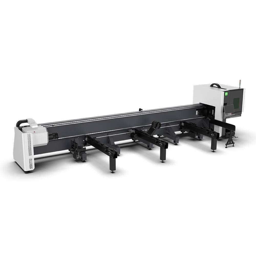
Advanced Fiber Laser Tube Processing Technology
Our CNC Fiber Laser Tube Cutting systems revolutionize metal fabrication by integrating high-precision cutting, punching, and profiling into a single automated workflow. Designed for versatility, this technology handles a wide array of profiles including Round, Square, Rectangular, and Oval tubes, as well as complex L-shaped and U-shaped channels.
- Precision Punching: High-speed hole punching with micron-level accuracy, eliminating the need for mechanical drilling or die-stamping.
- Complex Profiling: Advanced 3D pathing allows for intricate interlocking joints and specialized notch cuts, ideal for structural frames.
- High Material Efficiency: Intelligent nesting software minimizes scrap, reducing raw material costs across large production runs.
- Clean Finish: Delivers oxide-free, burr-free edges that require zero secondary grinding before welding.

Seamlessly processing multiple profiles with consistent precision.
Global Delivery & Logistics



From our high-tech manufacturing facility directly to your global site. PCL WeldCut ensures secure packaging, professional handling, and reliable international logistics to safeguard your equipment throughout the entire journey.