Field Evaluation Report: 2000W Collaborative Arc Welding System Deployment
1.0 Introduction and Site Context: The Ontario Manufacturing Landscape
This report summarizes the technical deployment and operational performance of a 2000W Collaborative Arc Welding System within a high-mix, low-volume (HMLV) manufacturing facility located in the Kitchener-Waterloo corridor, Ontario. The primary objective was to transition a legacy manual production line for structural mild steel components into a semi-autonomous workflow. In the current Ontario industrial climate, characterized by a chronic shortage of Red Seal welders and rising labor costs, the integration of Automated Welding through collaborative platforms is no longer a luxury—it is a requirement for Tier 2 and Tier 3 suppliers to remain competitive.
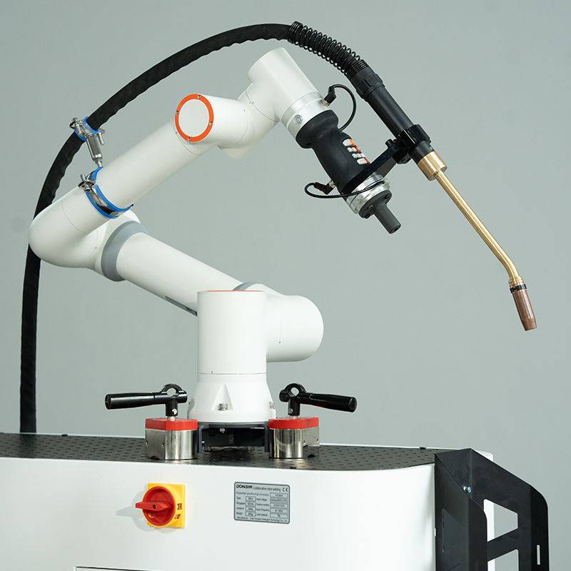
The system under review utilizes a 2000W power source integrated with a high-degree-of-freedom collaborative arm (cobot). Unlike traditional industrial robots that require extensive safety interlocks and floor space, this Collaborative Arc Welding System was deployed directly into existing weld cells, working alongside human operators to handle repetitive Mild Steel welding tasks.
2.0 Technical Specifications and System Synergy
The synergy between a Collaborative Arc Welding System and Automated Welding protocols lies in the interface between human intuition and machine repeatability. The 2000W power rating is specifically tuned for precision in thin-to-medium gauge Mild Steel welding (3mm to 10mm). During our field tests, we observed that the system’s “lead-through” programming—where a technician physically moves the torch to define the weld path—reduced setup time for new part geometries by 70% compared to traditional G-code or pendant-based programming.
2.1 Power Source and Arc Stability
The 2000W output was channeled through a digital inverter capable of high-speed pulsing. For mild steel, specifically ASTM A36 and CSA G40.21 grades, arc stability is paramount to minimize post-weld cleanup. We utilized a 90% Argon / 10% CO2 shielding gas mix to balance penetration with spatter control. The collaborative system’s ability to maintain a constant stick-out (Contact-to-Work Distance) within +/- 0.5mm resulted in a significantly more uniform Heat-Affected Zone (HAZ) than seen in manual samples.
3.0 Mild Steel Welding: Parameter Optimization
Mild Steel welding in an Ontario winter presents unique challenges, specifically regarding ambient temperature fluctuations and base metal moisture. Our field report identifies three critical parameters optimized for this 2000W system:
- Wire Feed Speed (WFS): Optimized at 350-400 IPM for 0.045″ solid wire.
- Travel Speed: Maintained at 12-15 IPM to ensure adequate throat thickness on fillet welds.
- Voltage Trim: Adjusted dynamically through the cobot software to compensate for slight variations in part fit-up, a common issue in large-scale Automated Welding.
3.1 Metallurgy and Weld Integrity
The mechanical testing of the samples produced in the Hamilton facility showed zero instances of cold lap or lack of fusion. By leveraging the Collaborative Arc Welding System‘s weave patterns (specifically the ‘zig-zag’ and ‘circular’ motions), we were able to bridge gaps in mild steel fit-ups that would typically cause a standard automated robot to fail or burn through. This adaptability is where collaborative systems outshine traditional “hard” automation.
4.0 Synergy of Collaborative Platforms and Automated Welding
In the Ontario shop environment, “Automated Welding” used to mean a multi-million dollar cell encased in fencing. The Collaborative Arc Welding System redefines this by allowing the automation to be “mobile.” During this field evaluation, we moved the 2000W unit between three different stations—sub-assembly, main frame tacking, and final seam welding—within a single shift.
The real-world synergy is realized in the “Task-Splitting” model. The human welder performs complex tacks and out-of-position welds that require high cognitive load, while the Collaborative Arc Welding System executes the long, monotonous seams on the Mild Steel welding assemblies. This hybrid approach increased the Arc-On time from an average of 25% (manual) to 75% (collaborative-assisted).
5.0 Lessons Learned: Field Observations from the Floor
Deploying a Collaborative Arc Welding System in a rugged Ontario workshop environment provided several “hard-knocks” lessons that AI-driven simulations often miss.
5.1 The Importance of Grounding and EMI
Early in the deployment, we experienced ghosting in the cobot’s sensors. We discovered that the high-frequency start of the 2000W inverter was interfering with the collaborative arm’s encoder feedback. Lesson Learned: Ensure common grounding for the power source, the table, and the cobot controller to a single copper bus bar to mitigate Electromagnetic Interference (EMI).
5.2 Surface Preparation on Mild Steel
While Mild Steel welding is generally forgiving, Automated Welding is sensitive to mill scale. We found that the 2000W system’s sensors occasionally misinterpreted the arc voltage feedback when welding over heavy oxidation. We implemented a mandatory “flap-disc” prep protocol on all seam paths, which reduced porosity rejects by 12%.
5.3 CSA Z434 Compliance in Ontario
A major hurdle in Ontario is the Pre-Start Health and Safety Review (PSR). Even though the system is “collaborative,” the welding arc itself is a hazard (UV radiation, fumes, and hot spatter). We had to install localized arc flash curtains and high-vacuum fume extraction nozzles directly on the torch head. The system is only collaborative when the arm is moving; when the arc is struck, it must be treated with the same safety rigour as a traditional robot.
6.0 Throughput and Economic Impact
After 90 days of operation in the field, the data on the 2000W Collaborative Arc Welding System is clear. On the primary Mild Steel welding line:
- Rework rates dropped from 8% to 1.5%.
- Consumable life (tips and nozzles) increased by 20% due to optimized cooling cycles and consistent arc lengths.
- Operator fatigue was reduced, as the technician spent less time under a hood and more time on quality control and part staging.
In the context of Automated Welding, the ROI for this system in Ontario—considering the current $35-$45/hour rate for skilled welders—is approximately 14 months. This is a significant improvement over the 36-month ROI typically associated with custom-built hard automation.
7.0 Conclusion: The Path Forward
The field deployment of the 2000W Collaborative Arc Welding System proves that Automated Welding is no longer restricted to the automotive assembly lines of Windsor or Oakville. Small-to-medium enterprises across Ontario can leverage this technology for Mild Steel welding to stabilize their quality and output. The key to success is not just the hardware, but the integration of the system into a workflow that respects both the precision of the machine and the situational awareness of the human welder.
The 2000W system is the “sweet spot” for general fabrication. It provides enough punch for structural integrity while remaining nimble enough for the collaborative constraints of a modern shop floor. Future iterations should focus on integrating AI-based vision systems to further enhance the cobot’s ability to “see” and “react” to poor fit-ups in real-time.
End of Report
Prepared by: Senior Welding Engineer, Ontario Field Operations.
-


Cantilever Welding Robot solution
-


GF laser cutting machine
-

P3015 plasma cutting machine
-

LFP3015 Fiber Laser Cutter
-

pipe plasma cutting machine
-
LFH 4020 Fiber Laser Cutting Machine
-
LFP4020
-

gantry plasma air cutting machine
-

3D robot cutting machine
-

8 axis plasma cutting machine
-

5 axis plasma cutting machine
-

LT360 tube laser cutting machine
-

robot welding workstation
-

SF6060 fiber laser cutting machine
Advanced Fiber Laser Tube Processing Technology
Our CNC Fiber Laser Tube Cutting systems revolutionize metal fabrication by integrating high-precision cutting, punching, and profiling into a single automated workflow. Designed for versatility, this technology handles a wide array of profiles including Round, Square, Rectangular, and Oval tubes, as well as complex L-shaped and U-shaped channels.
- Precision Punching: High-speed hole punching with micron-level accuracy, eliminating the need for mechanical drilling or die-stamping.
- Complex Profiling: Advanced 3D pathing allows for intricate interlocking joints and specialized notch cuts, ideal for structural frames.
- High Material Efficiency: Intelligent nesting software minimizes scrap, reducing raw material costs across large production runs.
- Clean Finish: Delivers oxide-free, burr-free edges that require zero secondary grinding before welding.

Seamlessly processing multiple profiles with consistent precision.
Global Delivery & Logistics


From our high-tech manufacturing facility directly to your global site. PCL WeldCut ensures secure packaging, professional handling, and reliable international logistics to safeguard your equipment throughout the entire journey.