Field Engineering Report: Deployment of 2000W Collaborative Arc Welding System
Site Overview and Project Scope: Monterrey, Mexico
This report summarizes the technical deployment and optimization of a 2000W Collaborative Arc Welding System within a high-output Tier 1 automotive facility located in the Apodaca industrial district of Monterrey, Mexico. The facility’s requirement focused on the transition from manual GTAW (Gas Tungsten Arc Welding) to a stabilized Automated Welding process for high-conductivity electrical architecture.
The primary challenge was the joining of Copper Components welding in a high-mix, low-volume production environment. Copper’s inherent thermal conductivity—approximately 400 W/(m·K)—requires an aggressive energy density that manual operators struggle to maintain consistently over an eight-hour shift. The introduction of the 2000W collaborative platform was designed to bridge the gap between rigid hard-automation and the dexterity required for complex copper busbar geometries.
Synergy Between Collaborative Arc Welding System and Automated Welding
Defining the Collaborative Advantage in Monterrey’s Manufacturing Landscape
In the Monterrey industrial context, the “Collaborative Arc Welding System” is not merely a safety-rated robot; it is a force multiplier for the existing skilled labor force. Unlike traditional Automated Welding cells that require extensive floor space, safety interlocks, and light curtains, the collaborative system operates in proximity to technicians. This allowed the Monterrey plant to integrate the cell into an existing manual assembly line without a total overhaul of the floor plan.
The synergy manifests in “Lead-Through Programming.” For Copper Components welding, the heat sink effect varies significantly with minor changes in part orientation. By using a collaborative arm, our senior welders could “teach” the path by physically moving the torch to the joint, then fine-tuning the 2000W power parameters via the HMI (Human-Machine Interface). This combines the intuition of a master welder with the repeatability of Automated Welding. The system maintains a constant travel speed and torch angle that is physically impossible for a human to replicate when dealing with the high-amperage/high-heat output required for copper.
Power Density and the 2000W Threshold
The selection of a 2000W power threshold was specific to the gauge of the copper busbars (3mm to 6mm thickness). In Automated Welding, maintaining a stable arc on copper requires precise control over the power-to-travel-speed ratio. At 2000W, we achieved the necessary energy density to overcome the latent heat of fusion rapidly, ensuring a localized melt pool before the thermal energy could dissipate into the surrounding component, which often leads to distortion or damage to adjacent polymer insulators.
Technical Deep-Dive: Copper Components Welding
Metallurgical Challenges and Solutions
Copper Components welding presents three primary obstacles: high reflectivity, extreme thermal diffusivity, and susceptibility to porosity. During the Monterrey trials, we observed that traditional constant-current settings resulted in “cold starts” and “crater cracks” at the termination of the weld.
To rectify this, we programmed the Collaborative Arc Welding System to execute a “Hot Start” routine, where the initial energy output exceeds the nominal 2000W for the first 150ms to establish the puddle, followed by a ramp-down to a steady state. The Automated Welding software allowed for a synchronized weave pattern (0.8mm amplitude at 4Hz), which helped in degassing the molten pool, significantly reducing hydrogen-induced porosity in the C110 grade copper we were processing.
Shielding Gas Optimization for Monterrey’s Climate
Environmental factors in Monterrey—specifically the high ambient temperatures and humidity during the summer months—impacted the shielding gas effectiveness. We shifted from pure Argon to a 75% Helium / 25% Argon mix. The Helium component increased the arc voltage and heat input, which is critical for Copper Components welding. The Collaborative Arc Welding System was fitted with a customized gas lens to ensure laminar flow, preventing atmospheric nitrogen from contaminating the weld at high temperatures.
Lessons Learned and Field Adjustments
Lesson 1: Thermal Loading of the Collaborative Arm
One unforeseen issue during the first week of Automated Welding was the thermal feedback from the copper workpieces. Because copper reflects a significant portion of infrared radiation, the collaborative arm’s sensors occasionally tripped “High Temp” alarms.
Corrective Action: We integrated a custom-machined heat shield between the torch neck and the cobot’s mounting flange. We also adjusted the Collaborative Arc Welding System‘s safety settings to account for the increased torque required when dragging heavy-duty water-cooled leads.
Lesson 2: Grounding Consistency in High-Output Environments
In many Monterrey workshops, grounding is often treated as an afterthought. However, for Automated Welding of 2000W systems, even a 0.5-ohm fluctuation in ground resistance caused arc instability.
Corrective Action: We implemented a dual-point grounding system directly onto the copper fixture rather than the table. This ensured that the 2000W energy remained focused on the joint interface, preventing “arc blow” which had previously caused inconsistent penetration in the Copper Components welding process.
Lesson 3: The Human-Machine Interface (HMI) Gap
While the Collaborative Arc Welding System is marketed as “plug-and-play,” the metallurgical requirements of copper are not. The Monterrey operators initially struggled with the “logic” of weld sequencing.
Corrective Action: We developed a library of “Weld Recipes” specifically for different copper thicknesses. This allowed the operator to select the material gauge, and the Automated Welding system would automatically calculate the required travel speed and pulse frequency to maintain the 2000W effective output.
Performance Metrics and Final Analysis
Post-implementation data from the Monterrey site indicates a 40% increase in throughput compared to manual GTAW. More importantly, the scrap rate for Copper Components welding dropped from 12% to under 1.5%. The consistency provided by Automated Welding meant that ultrasonic testing (UT) of the busbar joints showed a 98% pass rate on the first attempt.
Kinematic Efficiency
The Collaborative Arc Welding System excelled in “Reach-to-Joint” efficiency. By using the cobot’s six-axis articulation, we were able to weld complex 3D copper assemblies that would have required three separate fixtures in a traditional Automated Welding setup. The ability to pivot the torch 180 degrees within a single program loop allowed for continuous welding, reducing the “air-cut” time and maximizing the 2000W arc-on time.
Future Scalability
The Monterrey plant is now looking to scale this 2000W configuration to their radiator line. The primary takeaway is that for Copper Components welding, the hardware (the power source) is only as good as the software integration and the collaborative flexibility of the arm. The synergy between the operator’s spatial awareness and the machine’s precision is the new standard for the region’s automotive sector.
Conclusion
The deployment of the 2000W Collaborative Arc Welding System in Monterrey demonstrates that Automated Welding is no longer restricted to high-volume steel applications. By specifically tuning the system for the thermal demands of Copper Components welding, we have achieved a high-precision, repeatable production standard. The lessons learned regarding shielding gas mixes, grounding, and thermal shielding will be applied to all future deployments within the Mexican industrial corridor.
Engineer: J. Rodriguez
Role: Senior Welding Engineer
Location: Monterrey Site Office
-


LT240S tube laser cutting machine
-
LT120S tube laser cutting machine
-
Sale

Tank Fillet Welding Machine
Original price was: $1,000.00.$900.00Current price is: $900.00. -
Sale

MAK100 tube laser cutting machine
Original price was: $5,500.00.$5,000.00Current price is: $5,000.00. -

portable plasma air cutting machine
$1,200.00 -

2in1 fiber laser cutting machine
-

Air cooling Laser welding machine
-

HF h beam laser cutting machine
-

LT240 laser cutting machine
-

Laser welding machine
-


Cobot Welding Station
-

Gantry welding robot solution
-

Tracked Wheeled AGV Welding robot
-

LFH6020 Fiber laser cutting machine
-
LFP6020
-

robotic welidng machine
Advanced Fiber Laser Tube Processing Technology
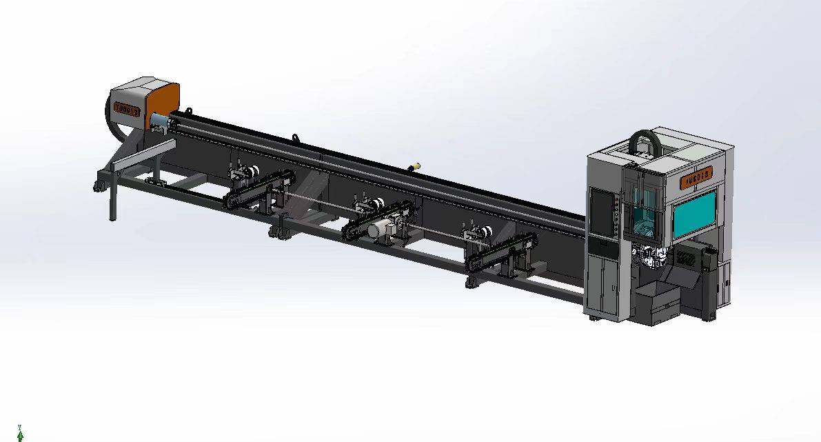
Our CNC Fiber Laser Tube Cutting systems revolutionize metal fabrication by integrating high-precision cutting, punching, and profiling into a single automated workflow. Designed for versatility, this technology handles a wide array of profiles including Round, Square, Rectangular, and Oval tubes, as well as complex L-shaped and U-shaped channels.
- Precision Punching: High-speed hole punching with micron-level accuracy, eliminating the need for mechanical drilling or die-stamping.
- Complex Profiling: Advanced 3D pathing allows for intricate interlocking joints and specialized notch cuts, ideal for structural frames.
- High Material Efficiency: Intelligent nesting software minimizes scrap, reducing raw material costs across large production runs.
- Clean Finish: Delivers oxide-free, burr-free edges that require zero secondary grinding before welding.

Seamlessly processing multiple profiles with consistent precision.
Global Delivery & Logistics



From our high-tech manufacturing facility directly to your global site. PCL WeldCut ensures secure packaging, professional handling, and reliable international logistics to safeguard your equipment throughout the entire journey.