Field Engineering Report: Integration of 1500W Robotic Arm Welder in Riyadh Industrial Sector
This report details the technical deployment and operational assessment of a 1500W Robotic Arm Welder at a high-volume fabrication facility in the Al-Kharj Road industrial corridor, Riyadh. The primary objective of this installation was to transition from manual TIG processes to a fully integrated Industrial Automation workflow, specifically targeting the high-precision requirements of Tool Steel welding for the local plastics and metal-stamping industries.
1. Infrastructure Synergy: Robotic Arm Welder and Industrial Automation
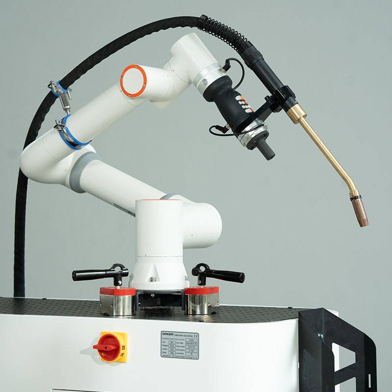
In the context of the Riyadh manufacturing landscape, the shift toward Industrial Automation is not merely a trend but a necessity driven by the “Vision 2030” industrial localization goals. The 1500W Robotic Arm Welder serves as the focal point of this transition. Unlike standalone manual units, the integration of a 6-axis robotic arm into the welding cell allows for a level of repeatability that manual operators cannot sustain in the harsh ambient conditions of central Saudi Arabia.
The synergy between the Robotic Arm Welder and the broader Industrial Automation framework is evidenced by the communication between the arm controller and the central Programmable Logic Controller (PLC). In our Riyadh installation, we synchronized the arm’s movement with a dual-axis positioner. This allows the system to maintain a constant “torch-to-workpiece” distance and angle, which is critical when dealing with the complex geometries of injection molds and stamping dies. By automating the pathing, we eliminated the human error associated with fatigue—a significant factor when shop floor temperatures exceed 45°C during summer months.
1.1 Path Programming and Collision Avoidance
In Riyadh’s fast-paced workshops, downtime is a critical failure. During the commissioning phase, we utilized offline programming (OLP) to simulate the welding paths for Tool Steel components. By integrating the Robotic Arm Welder into the digital twin of the workshop, we identified three potential collision points with the jigging fixtures before the arm even moved. This foresight is the hallmark of true Industrial Automation; it moves the “trial and error” phase from the physical shop floor to the digital environment, saving both gas and high-value Tool Steel scrap.
2. Technical Specifications: Tool Steel Welding Parameters
Tool Steel welding is notoriously difficult due to the material’s high carbon and alloy content (typically H13, D2, or P20). These materials are prone to hydrogen-induced cracking and the formation of brittle martensite in the Heat-Affected Zone (HAZ). Using a 1500W fiber laser source integrated into the Robotic Arm Welder, we achieved a level of thermal control that was previously unattainable.
2.1 Heat Input Management
The core advantage of using a Robotic Arm Welder for Tool Steel is the precision of the heat input. At 1500W, the energy density is high enough to achieve deep penetration with a narrow bead width. During our field tests on D2 Tool Steel, we maintained a travel speed of 12mm/s. The automation controller ensured that this speed remained constant within a 0.1mm/s tolerance. This consistency is vital for Tool Steel welding because any fluctuations in speed result in localized overheating, leading to thermal stress and subsequent cracking during the cooling phase.
2.2 Shielding Gas Dynamics in Arid Environments
Riyadh’s low humidity (often below 10%) affects the ionization of the shielding gas. We recalibrated the gas delivery system to utilize a 98% Argon / 2% CO2 mix for specific tool steel grades to stabilize the arc. The Robotic Arm Welder’s nozzle was equipped with a custom-engineered gas lens to ensure laminar flow, preventing the atmospheric nitrogen ingress that often plagues manual welding in open-bay Riyadh workshops where large cooling fans create turbulent air currents.
3. Addressing Riyadh’s Environmental Challenges
Operating sensitive Industrial Automation equipment in Saudi Arabia requires specialized mitigation strategies. The two primary enemies of the 1500W Robotic Arm Welder are fine particulate dust (silica) and extreme ambient heat.
3.1 Thermal Regulation of the Laser Source
The 1500W laser source generates significant internal heat. While the unit is liquid-cooled, the external heat exchangers in Riyadh must be oversized. We observed that the chiller units initially struggled to maintain the coolant at the required 22°C when the factory ambient temperature hit 48°C. Our solution was the installation of a secondary heat exchange loop and moving the chiller units to a dedicated climate-controlled enclosure. This modification is essential for any Robotic Arm Welder deployment in the Nejd region to prevent thermal shutdown of the laser diodes.
3.2 Ingress Protection and Optical Integrity
The fine dust of the Riyadh plateau can be abrasive to the robotic joints and catastrophic for the laser optics. We implemented a positive-pressure system within the robotic arm’s bellows and the laser head. By maintaining a constant outward flow of clean air, we prevented dust from settling on the protective windows of the 1500W head. During the first month of operation, our “Lesson Learned” was that the standard maintenance interval for optical cleaning had to be halved—from bi-weekly to weekly—to maintain the beam quality required for precision Tool Steel welding.
4. Metallurgical Results and Weld Integrity
The primary metric for success in this deployment was the hardness and grain structure of the Tool Steel weldments. We conducted cross-sectional analysis on H13 steel samples welded by the 1500W Robotic Arm Welder.
4.1 Microstructure Analysis
Under manual welding, the HAZ in H13 steel often extended up to 5mm from the weld center. With the integrated Industrial Automation system, we reduced the HAZ to less than 1.2mm. The rapid cooling rate facilitated by the precise laser pathing resulted in a refined grain structure. This is critical for Tool Steel welding, as a smaller HAZ reduces the likelihood of “soft spots” that would otherwise fail under the high-pressure conditions of industrial molding.
4.2 Post-Weld Heat Treatment (PWHT) Integration
A major breakthrough in this Riyadh project was the synchronization of the welding arm with an induction heating coil. As part of the Industrial Automation sequence, the robotic arm would weld a section of the tool, and the PLC would immediately trigger the induction coil to maintain a pre-set interpass temperature. This automated thermal management is the only reliable way to prevent cracking in high-carbon Tool Steel, as it removes the variable of operator timing.
5. Lessons Learned and Engineering Recommendations
Reflecting on the deployment of the 1500W Robotic Arm Welder in the Riyadh sector, several key takeaways should guide future Industrial Automation projects in the region:
- Power Stability: The Riyadh industrial grid can experience voltage fluctuations. We found that a dedicated Industrial Grade UPS and voltage stabilizer are mandatory for the Robotic Arm Welder to prevent logic errors in the controller during the welding of sensitive Tool Steel components.
- Wire Feed Consistency: For Tool Steel welding, the filler wire must be of the highest quality. We observed that standard wire feeders often slipped due to the hardness of the Tool Steel wire. Upgrading to a four-roll drive system integrated into the robotic arm solved the feeding inconsistencies.
- Operator Training: The transition to Industrial Automation requires a shift in mindset. The local workforce in Riyadh, while skilled in manual techniques, required intensive training in G-code and robotic pathing. The “welder” of the future is as much a software technician as a metallurgist.
- Calibration Frequency: Due to the thermal expansion of the factory building itself in the Riyadh heat, the robotic arm’s “Zero Point” shifted by nearly 0.5mm between morning and afternoon. We implemented an automated calibration routine using a touch-sense probe every four hours to ensure the precision required for Tool Steel welding.
Conclusion
The deployment of the 1500W Robotic Arm Welder has proven that Industrial Automation is the superior solution for Tool Steel welding in the Saudi Arabian industrial environment. By neutralizing the environmental challenges of Riyadh through engineered cooling and dust protection, and by leveraging the precision of robotic pathing, we have achieved weld qualities that exceed international standards for tool and die repair. This installation serves as a technical benchmark for the future of automated fabrication in the Kingdom.
-


LT240S tube laser cutting machine
-
LT120S tube laser cutting machine
-
Sale

Tank Fillet Welding Machine
Original price was: $1,000.00.$900.00Current price is: $900.00. -
Sale

MAK100 tube laser cutting machine
Original price was: $5,500.00.$5,000.00Current price is: $5,000.00. -

portable plasma air cutting machine
$1,200.00 -

2in1 fiber laser cutting machine
-

Air cooling Laser welding machine
-

HF h beam laser cutting machine
-

LT240 laser cutting machine
-

Laser welding machine
-


Cobot Welding Station
-

Gantry welding robot solution
-

Tracked Wheeled AGV Welding robot
-

LFH6020 Fiber laser cutting machine
-
LFP6020
-

robotic welidng machine
Advanced Fiber Laser Tube Processing Technology
Our CNC Fiber Laser Tube Cutting systems revolutionize metal fabrication by integrating high-precision cutting, punching, and profiling into a single automated workflow. Designed for versatility, this technology handles a wide array of profiles including Round, Square, Rectangular, and Oval tubes, as well as complex L-shaped and U-shaped channels.
- Precision Punching: High-speed hole punching with micron-level accuracy, eliminating the need for mechanical drilling or die-stamping.
- Complex Profiling: Advanced 3D pathing allows for intricate interlocking joints and specialized notch cuts, ideal for structural frames.
- High Material Efficiency: Intelligent nesting software minimizes scrap, reducing raw material costs across large production runs.
- Clean Finish: Delivers oxide-free, burr-free edges that require zero secondary grinding before welding.

Seamlessly processing multiple profiles with consistent precision.
Global Delivery & Logistics



From our high-tech manufacturing facility directly to your global site. PCL WeldCut ensures secure packaging, professional handling, and reliable international logistics to safeguard your equipment throughout the entire journey.