Field Engineering Report: Robotic Automation Commissioning (Gurgaon Sector 37)
Project Overview and Site Conditions
This report summarizes the deployment and optimization of a 1500W MIG/MAG Welding Robot at a heavy-tier automotive component facility in Gurgaon, India. The primary objective was to transition a manual multi-pass line to a fully automated cell capable of handling thick plate steel welding for structural chassis members. Gurgaon’s industrial environment presents specific challenges—predominantly high ambient temperatures (averaging 38°C during the shift) and significant airborne particulates typical of the Manesar-Gurgaon industrial belt. These factors necessitate a robust approach to cooling and wire-feed consistency.
The transition from manual labor to an automated MIG/MAG Welding Robot was not merely an upgrade in speed, but a required shift in metallurgical control. When dealing with structural components, the margin for error on penetration depth is zero. Our focus remained on the synergy between hardware kinematics and the specific Arc Welding Solutions implemented to mitigate heat-induced distortion in 12mm to 16mm plates.
System Architecture: The 1500W MIG/MAG Welding Robot
The core of the cell is a 6-axis articulated arm integrated with a 1500W power source management system. In the context of this installation, the “1500W” designation refers to the stabilized power consumption threshold for the inverter-based pulse control unit, optimized for high-duty cycle operations. Unlike standard manual sets, the MIG/MAG Welding Robot provides a level of repeatability in the “Torch-to-Work” distance that is humanly impossible over an 8-hour shift.
Kinematic Calibration and Wire Delivery
One of the first hurdles encountered in Gurgaon was the wire-feed consistency. We utilized a 1.2mm ER70S-6 solid wire. Due to the high humidity levels during the monsoon transition, we observed micro-oxidation on the wire surface which led to erratic arc stability. The solution was the integration of a pressurized wire-delivery drum and ceramic-lined conduits. For a MIG/MAG Welding Robot, any friction in the liner translates to “arc hunting,” which ruins the bead profile on Thick Plate Steel welding tasks. We recalibrated the feed motor torque parameters to ensure a constant wire speed of 10.5 m/min, which is our baseline for the root pass.
Implementing Advanced Arc Welding Solutions
The success of robotic automation in the Gurgaon workshop depended heavily on the software-driven Arc Welding Solutions we deployed. We are no longer just “burning wire”; we are managing a plasma column. We utilized a “Pulsed-Spray Transfer” mode to bridge the gap between deep penetration and spatter control.
Waveform Optimization
Standard short-circuit transfer was insufficient for the 15mm fillets required. By utilizing the proprietary Arc Welding Solutions embedded in the robot’s controller, we customized the pulse waveform. By shortening the “peak current” duration and slightly increasing the “base current,” we maintained a stable molten pool despite the high thermal conductivity of the Thick Plate Steel welding environment. This reduced post-weld cleaning time by 85% compared to the manual sets previously used on-site.
Seam Tracking and Adaptive Control
In a real-world Gurgaon factory, part fit-up is rarely perfect. Variations in plasma cutting tolerances meant the gap width on the thick plate joints varied by +/- 1.5mm. We implemented Through-Arc Seam Tracking (TAST). This allows the MIG/MAG Welding Robot to sense changes in the welding current as the stick-out fluctuates, automatically adjusting the torch path in real-time. This is where the synergy between the robot and the arc solution becomes profitable; without TAST, we would have seen a 12% reject rate due to lack of fusion at the root.
Technical Challenges in Thick Plate Steel Welding
Thick Plate Steel welding (10mm and above) requires a specific heat management strategy. If the interpass temperature exceeds 250°C, the grain structure of the heat-affected zone (HAZ) weakens, leading to potential structural failure under the vibration loads typical of Indian infrastructure equipment.
Managing Heat Input and Interpass Temps
During the Gurgaon trials, we found that the ambient heat was preventing the plates from cooling sufficiently between passes. We adjusted the robot’s duty cycle, implementing a “skip welding” sequence. The MIG/MAG Welding Robot was programmed to weld Segment A on the first workpiece, then immediately move to Workpiece B on a twin-station turntable. This allowed the Thick Plate Steel welding zones to cool naturally without stopping the production flow. This “Twin-Station” Arc Welding Solution effectively doubled our throughput while maintaining the metallurgical integrity of the steel.
Gas Shielding Dynamics in Open Workshops
The Gurgaon facility utilizes large overhead fans for worker comfort, which creates significant cross-drafts. For a MIG/MAG Welding Robot, cross-drafts are lethal as they strip the shielding gas (80% Argon / 20% CO2), leading to porosity. We moved from standard 15mm gas nozzles to 19mm high-flow “bottleneck” nozzles and increased the flow rate to 22 Liters/Minute. We also installed localized welding curtains. Field Note: Never underestimate the impact of a 50-inch industrial fan on robotic weld quality.
Lessons Learned and Engineering Observations
After three weeks of commissioning the 1500W system in Gurgaon, several “tribal knowledge” lessons emerged that are not found in the technical manuals.
1. Earthing and Grounding Consistency
On Thick Plate Steel welding, the current draw is substantial. We initially experienced “arc blow,” where the arc deflected wildly at the end of the seam. This was traced to poor earthing on the rotating jig. In robotic Arc Welding Solutions, the ground must be as consistent as the torch path. We moved to a dual-grounding brush system on the positioner, which stabilized the arc immediately.
2. Tip Consumables Longevity
The 1500W power source is aggressive on contact tips. In Gurgaon’s heat, we were burning through copper tips every 4 hours. We switched to Silver-plated Zirconium-Copper tips. While the unit cost is 3x higher, the lifespan increased to 20 hours of continuous “Arc-On” time. For a MIG/MAG Welding Robot, reducing the frequency of human intervention to change tips is key to ROI.
3. The Human-Robot Synergy
The most successful part of the Gurgaon deployment wasn’t just the MIG/MAG Welding Robot itself, but the training of the local manual welders to become “Robot Operators.” We taught them to recognize the sound of a “clean” pulse arc. Even with advanced Arc Welding Solutions, the operator’s ability to spot a misaligned wire or a clogged nozzle during the cycle start remains the final line of defense against scrap.
Conclusion: The Future of Fabrication in Gurgaon
The deployment of the 1500W system proves that high-precision MIG/MAG Welding Robot technology is viable even in harsh, high-temperature industrial environments. By focusing on Thick Plate Steel welding requirements—specifically penetration control and thermal management—we have moved the needle on local production quality. The integrated Arc Welding Solutions provided the necessary data feedback loops to ensure that the “Gurgaon Batch” meets international export standards. The project is now in the hand-over phase, with the cell running at 92% uptime efficiency.
Final Specification Summary:
- Process: Pulsed MIG (GMAW-P)
- Substrate: 12mm-16mm Mild Steel (Grade S355)
- Wire: 1.2mm Solid (ER70S-6)
- Gas: Ar + 20% CO2 @ 22L/min
- Target Output: 42 finished chassis units per shift.
-


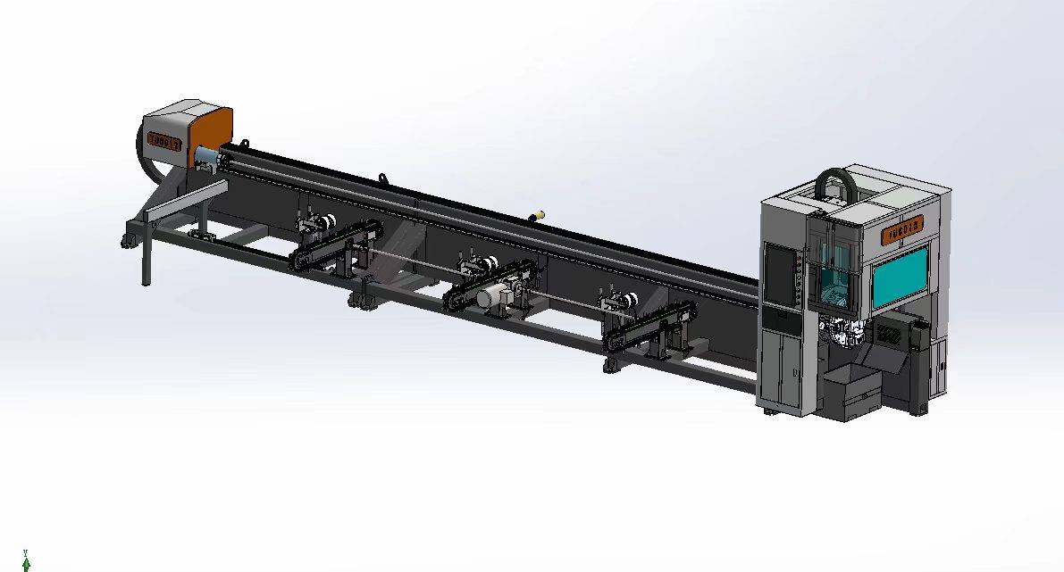
LT240S tube laser cutting machine
-
LT120S tube laser cutting machine
-
Sale

Tank Fillet Welding Machine
Original price was: $1,000.00.$900.00Current price is: $900.00. -
Sale

MAK100 tube laser cutting machine
Original price was: $5,500.00.$5,000.00Current price is: $5,000.00. -

portable plasma air cutting machine
$1,200.00 -

2in1 fiber laser cutting machine
-

Air cooling Laser welding machine
-

HF h beam laser cutting machine
-

LT240 laser cutting machine
-

Laser welding machine
-


Cobot Welding Station
-

Gantry welding robot solution
-

Tracked Wheeled AGV Welding robot
-

LFH6020 Fiber laser cutting machine
-
LFP6020
-

robotic welidng machine
Advanced Fiber Laser Tube Processing Technology
Our CNC Fiber Laser Tube Cutting systems revolutionize metal fabrication by integrating high-precision cutting, punching, and profiling into a single automated workflow. Designed for versatility, this technology handles a wide array of profiles including Round, Square, Rectangular, and Oval tubes, as well as complex L-shaped and U-shaped channels.
- Precision Punching: High-speed hole punching with micron-level accuracy, eliminating the need for mechanical drilling or die-stamping.
- Complex Profiling: Advanced 3D pathing allows for intricate interlocking joints and specialized notch cuts, ideal for structural frames.
- High Material Efficiency: Intelligent nesting software minimizes scrap, reducing raw material costs across large production runs.
- Clean Finish: Delivers oxide-free, burr-free edges that require zero secondary grinding before welding.

Seamlessly processing multiple profiles with consistent precision.
Global Delivery & Logistics


From our high-tech manufacturing facility directly to your global site. PCL WeldCut ensures secure packaging, professional handling, and reliable international logistics to safeguard your equipment throughout the entire journey.