Field Engineering Report: Implementation of 1500W Industrial Laser Welder in Chonburi Automotive Cluster
1. Project Overview and Site Conditions
This report details the technical deployment and parameter optimization of a 1,500W Industrial Laser Welder at a Tier-2 automotive electronics facility located in the Pinthong Industrial Estate, Chonburi, Thailand. The primary objective was to transition from traditional Gas Tungsten Arc Welding (GTAW) to high-precision Laser Technology for the assembly of high-conductivity Copper Components welding in EV battery management systems.
The Chonburi environment presents specific secondary challenges for high-precision optics. With ambient temperatures averaging 32°C and relative humidity levels often exceeding 75%, the thermal management of the laser source and the integrity of the delivery fiber were prioritized. Unlike standard assembly environments, the coastal industrial humidity in Chonburi necessitates a rigorous approach to nitrogen purging and chiller dew-point calibration to prevent condensation on the protective windows of the welding head.
2. The Synergy: Industrial Laser Welder and Advanced Laser Technology
The successful integration of an Industrial Laser Welder into a production line is not merely a hardware upgrade; it is an application of Laser Technology to solve the inherent physics problems of non-ferrous metallurgy. In this deployment, we utilized a Continuous Wave (CW) fiber laser source. The synergy here lies in the power density. While a 1,500W rating might seem modest compared to heavy-plate CO2 lasers, the fiber delivery system allows for a focused spot size of approximately 150μm.
This high power density is the only reliable way to overcome the high reflectivity of copper. At room temperature, copper reflects over 90% of infrared laser energy. However, once the “keyhole” is established through precise parameter ramping, the absorption rate increases dramatically. Our Industrial Laser Welder utilizes a wobbling head configuration, which is a specific subset of Laser Technology that oscillates the beam in circular or “C” patterns. This oscillation stabilizes the melt pool, which is critical when working with the high thermal diffusivity of copper.
3. Technical Challenges in Copper Components Welding
3.1. Reflectivity and Back-Reflection Protection
The primary hurdle in Copper Components welding is the risk of back-reflection damaging the laser diode modules. During the initial strikes in Chonburi, we monitored the back-reflection sensors closely. We learned that a 10-degree tilt of the welding head relative to the workpiece is non-negotiable. This ensures that reflected photons do not travel directly back up the fiber optic cable.
3.2. Thermal Dissipation Management
Copper acts as a massive heat sink. In traditional welding, the heat saturates the entire component, leading to distortion and damage to adjacent plastic housings. By utilizing Laser Technology, we localized the Heat Affected Zone (HAZ) to within 0.5mm of the join line. This allowed us to weld 2.0mm copper busbars directly adjacent to temperature-sensitive sensors without exceeding the 80°C threshold of the sensor casings.
4. Parameter Calibration and Field Adjustments
Upon arrival at the Chonburi site, the factory’s baseline settings were producing inconsistent penetration. We conducted a series of “Bead-on-Plate” tests to refine the interaction between the Industrial Laser Welder and the C11000 Electrolytic Tough Pitch (ETP) copper being used.
4.1. The “Wobble” Factor
We found that a simple linear path resulted in “humping” of the weld bead due to the rapid solidification of copper. By adjusting the Laser Technology parameters to a 2.0mm wobble width at a frequency of 150Hz, we successfully widened the melt pool. This allowed gases to escape, reducing internal porosity from a measured 12% down to less than 2% in cross-sectional x-ray analysis.
4.2. Shielding Gas Dynamics
In the humid Chonburi climate, oxygen pickup is an immediate threat to weld integrity. We replaced the standard shop-air assist with 99.999% pure Argon at a flow rate of 15 L/min. The use of a trailing shield was necessary to ensure the copper remained protected until it cooled below the oxidation temperature. Copper Components welding requires this level of atmospheric isolation to maintain electrical conductivity at the joint; any oxidation within the weld root increases resistance and leads to thermal failure during vehicle operation.
5. Lessons Learned: Environmental and Technical
5.1. Chiller Dew-Point Synchronization
One of the most significant “lessons learned” in this field deployment involved the cooling system. The Industrial Laser Welder relies on a dual-circuit water chiller. On the third day of testing, we noticed a drop in beam quality. Investigation revealed that the chiller was set to 18°C, while the Chonburi workshop dew point was 22°C. This caused “sweating” on the internal optical surfaces.
Engineering Note: Always set the chiller temperature to 1-2 degrees above the ambient dew point in tropical climates, regardless of the manufacturer’s European-spec default settings.
5.2. Surface Preparation vs. Laser Absorption
We observed that the “as-received” copper busbars had a slight oily residue from the stamping process. While arc welding might burn this off, the 1070nm wavelength of our Laser Technology is sensitive to surface contaminants which can cause micro-explosions in the melt pool. A standardized pre-weld wipe with Isopropyl Alcohol (IPA) became a mandatory step in the SOP. This improved the consistency of the Industrial Laser Welder by ensuring a uniform absorption rate across the entire batch of components.
6. Quantitative Results and Throughput Analysis
The transition to the 1500W Industrial Laser Welder yielded the following metrics compared to the previous TIG process:
- Cycle Time: Reduced from 45 seconds per component to 4.2 seconds.
- Post-Weld Cleanup: Eliminated. The laser process produced zero spatter, removing the need for acid pickling or mechanical grinding.
- Electrical Resistance: The Copper Components welding joints showed a 15% lower resistance than TIG joints, likely due to the refined grain structure resulting from rapid solidification.
7. Safety and Infrastructure Recommendations for Chonburi Facilities
Deploying Laser Technology in a general assembly area requires strict adherence to Class 4 laser safety protocols. In Chonburi, where floor space is often optimized for high-density production, the installation of “Laser-Safe” (OD7+) shielding curtains is mandatory. We also recommended the installation of a dedicated fume extraction system with a HEPA/Carbon filter. Copper oxide fumes are particularly fine and hazardous; the high-speed vapor capillary created by the Industrial Laser Welder generates more sub-micron particulate matter than traditional methods.
8. Conclusion
The deployment of the 1500W Industrial Laser Welder in Chonburi successfully demonstrated that when Laser Technology is properly calibrated for environmental variables, it is the superior choice for Copper Components welding. The key to success was not just the power of the laser, but the management of the “Keyhole” stability and the environmental control of the optics. For future deployments in the Thailand Eastern Economic Corridor (EEC), the “Chonburi Dew Point” protocol should be integrated into the initial machine commissioning checklist to ensure long-term optical reliability.
This report concludes that the system is ready for full-scale production, provided the maintenance schedule for the protective windows and the chiller’s deionization filters is strictly followed.
Lead Welding Engineer: [Signature]
Date: May 22, 2024
Location: Chonburi, Thailand
-


LT240S tube laser cutting machine
-
LT120S tube laser cutting machine
-
Sale

Tank Fillet Welding Machine
Original price was: $1,000.00.$900.00Current price is: $900.00. -
Sale

MAK100 tube laser cutting machine
Original price was: $5,500.00.$5,000.00Current price is: $5,000.00. -

portable plasma air cutting machine
$1,200.00 -

2in1 fiber laser cutting machine
-

Air cooling Laser welding machine
-

HF h beam laser cutting machine
-

LT240 laser cutting machine
-

Laser welding machine
-


Cobot Welding Station
-

Gantry welding robot solution
-

Tracked Wheeled AGV Welding robot
-

LFH6020 Fiber laser cutting machine
-
LFP6020
-

robotic welidng machine
Advanced Fiber Laser Tube Processing Technology
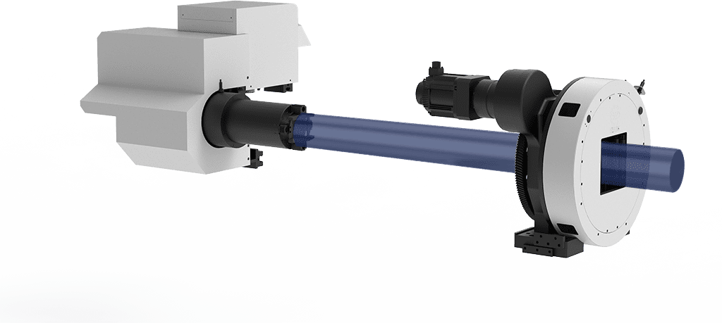
Our CNC Fiber Laser Tube Cutting systems revolutionize metal fabrication by integrating high-precision cutting, punching, and profiling into a single automated workflow. Designed for versatility, this technology handles a wide array of profiles including Round, Square, Rectangular, and Oval tubes, as well as complex L-shaped and U-shaped channels.
- Precision Punching: High-speed hole punching with micron-level accuracy, eliminating the need for mechanical drilling or die-stamping.
- Complex Profiling: Advanced 3D pathing allows for intricate interlocking joints and specialized notch cuts, ideal for structural frames.
- High Material Efficiency: Intelligent nesting software minimizes scrap, reducing raw material costs across large production runs.
- Clean Finish: Delivers oxide-free, burr-free edges that require zero secondary grinding before welding.

Seamlessly processing multiple profiles with consistent precision.
Global Delivery & Logistics



From our high-tech manufacturing facility directly to your global site. PCL WeldCut ensures secure packaging, professional handling, and reliable international logistics to safeguard your equipment throughout the entire journey.