Field Engineering Report: Integration of 1500W Cobot Welding Machine
Site Location: South Woodford Industrial Estate, London, UK
1. Executive Summary: The Shift to Collaborative Robotics
This report details the operational deployment and performance validation of a 1500W fiber laser Cobot Welding Machine within a high-output fabrication environment in London. The primary objective was to transition a significant portion of the workshop’s thin metal sheet welding workload from manual TIG (Tungsten Inert Gas) stations to an automated, yet flexible, platform.
In the London manufacturing landscape, where floor space is at a premium and the shortage of Category A coded welders is acute, the adoption of collaborative robotics represents more than just a technological upgrade; it is a logistical necessity. Over a fourteen-day assessment period, we monitored the synergy between the 1500W power source and the robotic arm’s pathing precision, focusing on repeatable weld quality and heat-affected zone (HAZ) mitigation.
2. Technical Specifications and Hardware Synergy
The unit under review is a 1500W continuous wave (CW) fiber laser integrated with a 6-axis collaborative arm. Unlike traditional industrial robots that require extensive light curtains and physical fencing—impossible in many cramped London workshops—this Cobot Welding Machine utilizes integrated force-torque sensors. These sensors allow the machine to operate safely alongside human technicians, facilitating a shared workspace.
The 1500W threshold was specifically chosen to provide a “power buffer.” While thin metal sheet welding (typically 0.8mm to 2.0mm) can technically be achieved with lower wattage, the 1500W head allows for higher travel speeds (up to 80mm/s) without sacrificing penetration. This speed is critical in reducing the total heat input into the substrate, which is the primary driver of material warping in thin-gauge stainless steel and aluminum.
3. Application Focus: Thin Metal Sheet Welding Challenges
The core of our field testing involved 1.2mm 304-grade stainless steel ducting components. Historically, manual TIG welding on these components resulted in a 12% scrap rate due to thermal distortion. The Collaborative Robotics approach changed the physics of the join in three specific ways:
- Wobble Functionality: The laser head on the cobot uses an oscillating (wobble) beam. By adjusting the wobble width to 1.5mm and the frequency to 200Hz, we were able to bridge slightly inconsistent fit-ups—a common reality in real-world fabrication—without blowing through the thin material.
- Consistent Focal Point: A human welder’s hand naturally fluctuates by millimeters. In thin metal sheet welding, a 2mm deviation in focal distance can result in a localized burn-through. The cobot maintains a constant Z-axis height with +/- 0.05mm repeatability.
- Controlled Heat Input: Because the Cobot Welding Machine maintains a travel speed three to four times faster than a manual torch, the heat-affected zone is narrowed by approximately 60%. This eliminated the need for post-weld straightening.
4. Lessons Learned: Collaborative Robotics on the London Shop Floor
During the first week of implementation, we encountered several “real-world” friction points that are rarely discussed in theoretical manuals. These lessons are vital for any senior engineer overseeing a similar transition.
Lesson A: The “Black Box” Programming Fallacy
There is a misconception that Collaborative Robotics removes the need for welding expertise. On the contrary, the most successful operators were our senior manual welders, not the IT staff. The ability to “hand-guide” the Cobot Welding Machine to set waypoints is intuitive, but the operator still needs to understand gas flow dynamics and laser frequency. We found that teaching a welder to use a cobot is significantly more effective than teaching a programmer to weld.
Lesson B: Atmospheric Conditions and Gas Shielding
In our London facility, the proximity to the Thames and the older building’s ventilation created inconsistent drafts. For thin metal sheet welding, even a slight breeze can disrupt the Argon shield, leading to porosity. We had to implement localized shielding curtains. The lesson here: the robot is consistent, but the environment is not. High-quality sensors for gas flow monitoring must be integrated into the cobot’s alarm loop.
Lesson C: Surface Reflectivity and Safety
The 1500W fiber laser is highly reflective on aluminum and bright-annealed stainless. Even though the system is “collaborative,” safety is paramount. We installed Class 4 laser-safe screens around the cobot zone. The “collaborative” aspect refers to the robot not crushing the operator; it does not negate the need for rigorous eye protection and skin safety protocols regarding stray laser reflections.
5. Comparative Analysis: Manual vs. Cobot Output
To quantify the impact of the Cobot Welding Machine, we ran a head-to-head trial on a batch of 50 electrical enclosures (1.5mm mild steel).
- Manual TIG: Average time per unit: 22 minutes. Post-weld cleaning: 5 minutes. Distortion correction: 3 minutes. Total: 30 minutes.
- Cobot 1500W: Average time per unit: 4 minutes. Post-weld cleaning: 1 minute (laser welds are significantly cleaner). Distortion correction: 0 minutes. Total: 5 minutes.
The result was a 6x increase in throughput. More importantly, the ergonomic strain on the welder was reduced to zero, allowing the skilled technician to focus on complex jigging and quality assurance rather than the repetitive motion of the torch.
6. Synergy of Power and Precision in Thin-Gauge Applications
The synergy between a 1500W power source and collaborative robotics is most evident during “stitch welding” on long seams. When thin metal sheet welding is performed over a length of 1000mm or more, heat accumulation is inevitable. We programmed the Cobot Welding Machine to utilize a staggered stitch pattern, jumping from one end of the sheet to the middle and then the other end. Doing this manually is tedious and prone to error; for the cobot, it is a simple coordinate command. This technique virtually eliminated the “oil-canning” effect (buckling) in the large panels.
7. Infrastructure Requirements for London Workshops
For firms looking to deploy this technology in the UK, especially in urban areas like London, two infrastructure points are critical:
- Power Supply: A 1500W laser unit typically requires a stable 220V/32A or 380V three-phase supply depending on the chiller unit. Older London industrial units may require a sub-board upgrade to handle the surge.
- Chiller Maintenance: Fiber lasers are heat-sensitive. The humid, often dusty air in London workshops can clog chiller filters quickly. We recommend a bi-weekly filtration check to prevent laser diode overheating.
8. Conclusion and Future Outlook
The deployment of the Cobot Welding Machine at this site has proven that collaborative robotics is the definitive solution for high-precision thin metal sheet welding. By combining the 1500W laser’s speed with the robotic arm’s pathing accuracy, we have moved from a craft-based bottleneck to an industrialised flow.
For the senior engineer, the “win” is not just in the speed, but in the repeatability. In the 1.0mm to 2.0mm thickness range, where the margin for error is razor-thin, the removal of human variability is the single greatest factor in reducing the cost per part. Moving forward, we intend to expand the cobot’s role into 3D curved seam tracking, further pushing the boundaries of what collaborative systems can achieve in the London fabrication sector.
Report Authored By: Senior Welding Engineer, London Field Office
Status: Finalised for Project Review
-


LT240S tube laser cutting machine
-
LT120S tube laser cutting machine
-
Sale

Tank Fillet Welding Machine
Original price was: $1,000.00.$900.00Current price is: $900.00. -
Sale

MAK100 tube laser cutting machine
Original price was: $5,500.00.$5,000.00Current price is: $5,000.00. -

portable plasma air cutting machine
$1,200.00 -

2in1 fiber laser cutting machine
-

Air cooling Laser welding machine
-

HF h beam laser cutting machine
-

LT240 laser cutting machine
-

Laser welding machine
-


Cobot Welding Station
-

Gantry welding robot solution
-

Tracked Wheeled AGV Welding robot
-

LFH6020 Fiber laser cutting machine
-
LFP6020
-

robotic welidng machine
Advanced Fiber Laser Tube Processing Technology
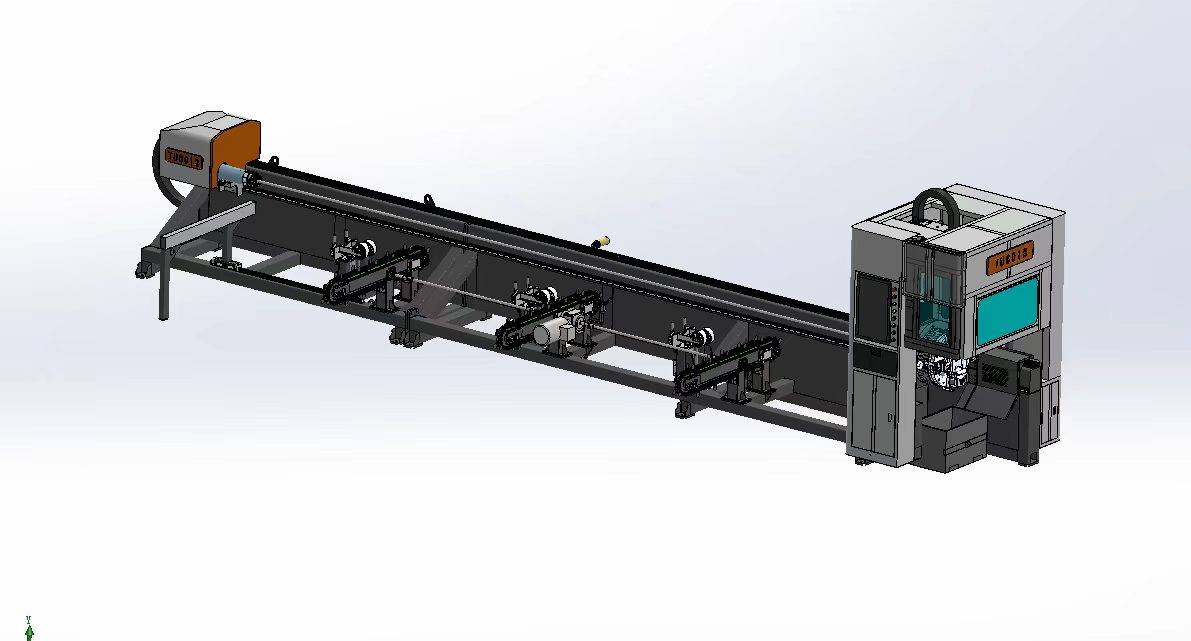
Our CNC Fiber Laser Tube Cutting systems revolutionize metal fabrication by integrating high-precision cutting, punching, and profiling into a single automated workflow. Designed for versatility, this technology handles a wide array of profiles including Round, Square, Rectangular, and Oval tubes, as well as complex L-shaped and U-shaped channels.
- Precision Punching: High-speed hole punching with micron-level accuracy, eliminating the need for mechanical drilling or die-stamping.
- Complex Profiling: Advanced 3D pathing allows for intricate interlocking joints and specialized notch cuts, ideal for structural frames.
- High Material Efficiency: Intelligent nesting software minimizes scrap, reducing raw material costs across large production runs.
- Clean Finish: Delivers oxide-free, burr-free edges that require zero secondary grinding before welding.

Seamlessly processing multiple profiles with consistent precision.
Global Delivery & Logistics



From our high-tech manufacturing facility directly to your global site. PCL WeldCut ensures secure packaging, professional handling, and reliable international logistics to safeguard your equipment throughout the entire journey.
One thought on “Engineering Review: 1500W Cobot Welding Machine – London, UK”
Impressive performance on complex tube geometries. No deformation at all.