Field Report: Deployment of 1000W Cobot Welding Machine in Ontario Tooling Environments
Introduction and Regional Context
In the current manufacturing landscape of the Golden Horseshoe and Southwestern Ontario, the deficit of high-precision manual welders has reached a critical inflection point. This report details the field deployment and performance metrics of a 1000W Cobot Welding Machine integrated into a Tier-2 automotive tooling facility in Windsor, Ontario. The objective was to transition from manual GTAW (Gas Tungsten Arc Welding) to an automated, collaborative system specifically for the refurbishment of high-injection mold components and die-casting inserts.
The implementation of Collaborative Robotics in this sector is not merely a play for speed; it is a strategy for consistency. In Ontario, where CSA Z434-14 standards govern industrial robot safety, the 1000W Cobot Welding Machine provides a unique middle ground—allowing the operator to remain in proximity to the weldment for real-time adjustments while the machine handles the precision torch oscillations required for Tool Steel welding.
The Technical Synergy of Collaborative Robotics and 1000W Systems
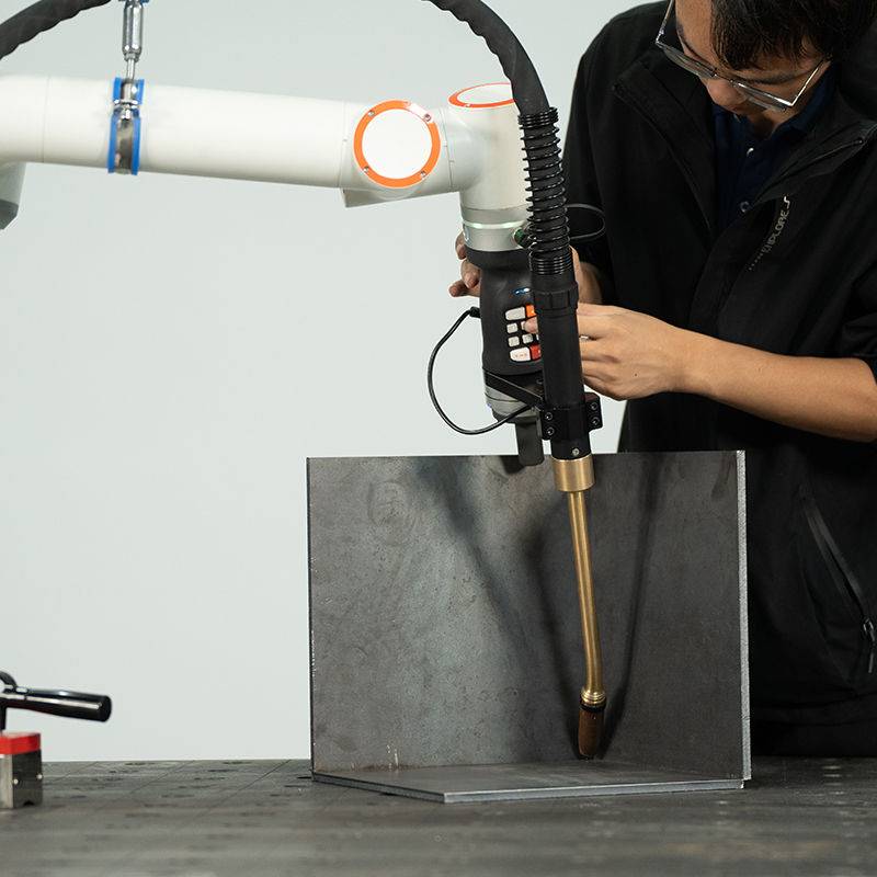
The synergy between the Cobot Welding Machine and the philosophy of Collaborative Robotics lies in the democratization of high-end welding parameters. Traditionally, a 1000W fiber laser or pulsed-power source required a rigid, caged-in Cartesian or 6-axis industrial robot. However, the modern Ontario shop floor lacks the footprint for massive work cells. By utilizing a cobot, we leverage force-torque sensors and simplified lead-through programming.
During the field test, we observed that the “collaborative” aspect allowed our lead mold makers to “teach” the path by hand. This is vital when dealing with the complex, non-linear geometries of injection molds. The machine isn’t replacing the welder; it is acting as a high-precision steadier of the arc. The 1000W power supply, specifically tuned for a high-duty cycle, ensures that the thermal density is sufficient for deep penetration without the excessive heat-affected zone (HAZ) typically associated with manual stick or heavy MIG processes.
Application Focus: Tool Steel Welding Parameters
Tool Steel welding (specifically H13, P20, and S7) is notoriously unforgiving. The primary challenge in Ontario’s tool and die sector is “cold cracking” and the formation of untempered martensite in the HAZ. Our field data focused on H13 tool steel inserts used in high-pressure die casting.
Heat Input Management and Cracking Prevention
When using the Cobot Welding Machine, we implemented a pulsed-wave logic that manual operators struggle to maintain over a 10-inch pass. For H13 material, we maintained a strict interpass temperature of 250°C. The Collaborative Robotics system was programmed to pause at specific nodes to allow for thermal dissipation, monitored by integrated infrared sensors.
The 1000W output was modulated at a frequency of 15Hz with a 30% duty cycle for the root pass. This specific configuration allowed for a localized melt pool that solidified rapidly enough to prevent grain coarsening, but slowly enough to avoid the brittleness common in tool steel repairs. Manual GTAW often results in a “humped” bead profile which requires excessive post-weld machining; the cobot’s ability to maintain a constant 1.2mm/s travel speed resulted in a flat, uniform bead that reduced CNC finishing time by 40%.
Filler Wire Integration
A critical lesson learned during the Ontario deployment was the sensitivity of the wire feed speed (WFS) in collaborative setups. We utilized a 0.030″ ER420 filler wire. The Cobot Welding Machine’s controller was synced with the wire feeder to provide a “pull-back” at the end of each pulse. This eliminated the “crater crack” at the end of the tool steel weld, which is the most common failure point in mold repair. By automating the termination sequence via the cobot’s software, we removed the variability of the human hand at the most sensitive part of the weld cycle.
Ontario-Specific Environmental and Regulatory Challenges
Deploying industrial hardware in Ontario requires adherence to specific electrical and safety codes that differ from US or European standards. The 1000W units used were CSA-compliant, but we encountered specific issues regarding the “Collaborative” classification under Ontario Ministry of Labour guidelines.
Safety and Risk Assessment
Even though the machine is a “Cobot,” the 1000W welding arc (particularly if laser-based or high-amperage plasma/MIG) introduces radiation and fume hazards. In this field application, we utilized a “Power and Force Limiting” (PFL) strategy for the robot movement, but we had to implement a localized high-intensity light curtain. Lessons learned: Do not assume the “Cobot” label exempts the cell from a Pre-Start Health and Safety Review (PSR) in Ontario. If the process (the arc) is hazardous, the collaboration must be strictly controlled with specialized PPE and fume extraction (minimum 800 CFM at the source).
Climate Control and Grid Stability
The Southwestern Ontario power grid, while generally stable, can see fluctuations in industrial parks. We observed that the 1000W power source required a dedicated line conditioner to prevent “arc stutter” during peak summer demand hours when local HVAC loads were high. Furthermore, the high humidity levels in Ontario summers led to condensation issues in the coolant lines of the cobot’s torch. We moved to a closed-loop refrigerated chiller system to maintain a constant 20°C for the power source, preventing the internal electronics from tripping due to moisture ingress.
Lessons Learned and Technical Optimizations
1. Path Smoothing and Singularity Avoidance
One of the technical hurdles encountered was “singularity” in the cobot’s arm when welding inside deep pockets of a tool steel mold. When the cobot’s joints align, it loses a degree of freedom, causing a stutter in the weld bead.
Solution: We re-oriented the workpiece on a 45-degree tilt table. This kept the cobot in its optimal “work envelope” and ensured the 1000W energy delivery remained perpendicular to the joint, which is essential for consistent Tool Steel welding penetration.
2. Programming for Real-World Geometry
Tools are rarely “as-built” according to the original CAD after years of service. A “blind” robotic program will fail. The success of the Collaborative Robotics approach here was the use of “Touch-Sensing.” We programmed the cobot to use the welding wire to touch three points on the tool steel insert to “find” the part in 3D space. This auto-correction accounted for the 2-3mm of thermal warping present in the used die.
3. Gas Shielding in Open Environments
Because Cobot Welding Machines are often used in open shop environments (without the full enclosures of traditional robots), cross-drafts are a major concern. In the Ontario facility, overhead bay doors created intermittent drafts that caused porosity in the H13 tool steel welds.
Lesson learned: We increased the Argon flow to 35 CFH and utilized a jumbo gas lens with a localized “tenting” shield attached to the cobot’s end-effector. This maintained a laminar flow over the weld pool regardless of the shop’s ambient air movement.
Economic and Metallurgical Outcomes
After six months of field operation in Ontario, the data supports the following conclusions:
- Hardness Retention: Post-weld Rockwell C (HRC) testing showed a consistent 52-54 HRC in the weld zone of H13 inserts, matching the base metal after a single tempering cycle. This is a 15% improvement over manual GTAW results, which often showed “soft spots” due to inconsistent heat input.
- Cycle Time: While the “arc-on” time is similar to manual welding, the “total time to part” dropped significantly. The cobot’s ability to weld at a 90% duty cycle meant that large tool steel repairs that previously took two shifts were completed in four hours.
- Labor Allocation: The shop’s senior welder now manages three Cobot Welding Machines simultaneously. He sets the parameters and performs the initial “teach,” while junior operators swap parts and monitor the cycles. This has effectively tripled the shop’s capacity without adding headcount.
Final Engineering Summary
The 1000W Cobot Welding Machine is the most viable path forward for Ontario’s mold and die industry. The marriage of Collaborative Robotics and precision Tool Steel welding protocols addresses the primary pain points of the region: labor shortages and the need for metallurgical precision. For successful implementation, engineers must look beyond the robot arm and focus on the integration of power-source stability, CSA-compliant safety boundaries, and rigorous thermal management of the tool steel substrate. The “collaborative” nature of the machine is its greatest strength, provided the operator understands that the machine is a tool of precision, not a “set-and-forget” solution.
-


LT240S tube laser cutting machine
-
LT120S tube laser cutting machine
-
Sale

Tank Fillet Welding Machine
Original price was: $1,000.00.$900.00Current price is: $900.00. -
Sale

MAK100 tube laser cutting machine
Original price was: $5,500.00.$5,000.00Current price is: $5,000.00. -

portable plasma air cutting machine
$1,200.00 -

2in1 fiber laser cutting machine
-

Air cooling Laser welding machine
-

HF h beam laser cutting machine
-

LT240 laser cutting machine
-

Laser welding machine
-


Cobot Welding Station
-

Gantry welding robot solution
-

Tracked Wheeled AGV Welding robot
-

LFH6020 Fiber laser cutting machine
-
LFP6020
-

robotic welidng machine
Advanced Fiber Laser Tube Processing Technology
Our CNC Fiber Laser Tube Cutting systems revolutionize metal fabrication by integrating high-precision cutting, punching, and profiling into a single automated workflow. Designed for versatility, this technology handles a wide array of profiles including Round, Square, Rectangular, and Oval tubes, as well as complex L-shaped and U-shaped channels.
- Precision Punching: High-speed hole punching with micron-level accuracy, eliminating the need for mechanical drilling or die-stamping.
- Complex Profiling: Advanced 3D pathing allows for intricate interlocking joints and specialized notch cuts, ideal for structural frames.
- High Material Efficiency: Intelligent nesting software minimizes scrap, reducing raw material costs across large production runs.
- Clean Finish: Delivers oxide-free, burr-free edges that require zero secondary grinding before welding.

Seamlessly processing multiple profiles with consistent precision.
Global Delivery & Logistics


From our high-tech manufacturing facility directly to your global site. PCL WeldCut ensures secure packaging, professional handling, and reliable international logistics to safeguard your equipment throughout the entire journey.