Engineering Review: 1000W Robotic Arm Welder – Busan, South Korea
In this article
- Field Evaluation: 1000W Robotic Arm Welder Integration in Busan Industrial Zone
- 1. Executive Summary and Site Overview
- 2. The Synergy: Robotic Arm Welder and Industrial Automation
- 3. Technical Deep-Dive: Thin Metal Sheet Welding Challenges
- 4. Lessons Learned: Environmental and Technical Constraints
- 5. Impact on the Busan Workshop Operations
- 6. Conclusion and Future Recommendations
Field Evaluation: 1000W Robotic Arm Welder Integration in Busan Industrial Zone
1. Executive Summary and Site Overview
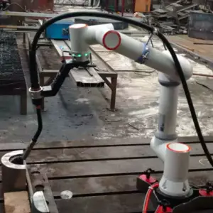
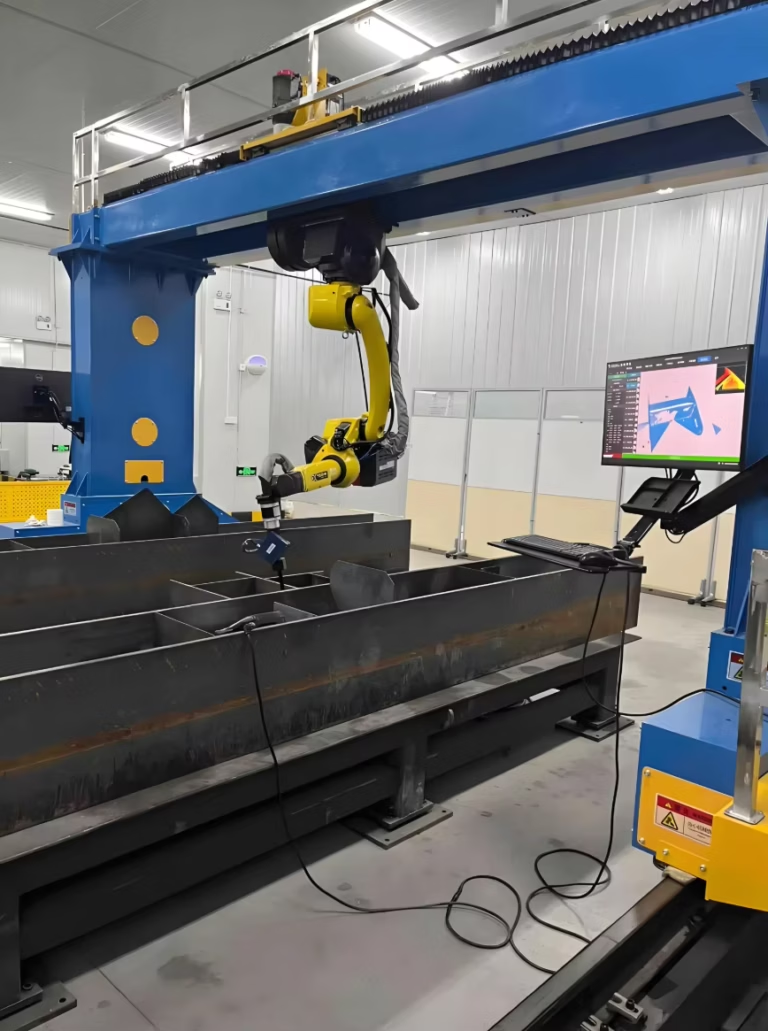
This report details the technical deployment and optimization of a 1000W fiber-delivered Robotic Arm Welder within a Tier-2 automotive component facility located in the Gangseo-gu industrial district of Busan, South Korea. The primary objective of the field visit was to finalize the integration of Industrial Automation protocols for a high-volume production line specializing in Thin Metal Sheet welding (specifically 0.8mm to 1.2mm STS304 and AL5052 alloys).
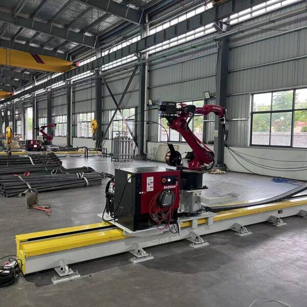
The Busan facility operates under a high-humidity coastal environment, which presented unique challenges for gas shielding and electronic stability. The installation involves a 6-axis articulated robotic arm coupled with a 1000W continuous wave (CW) fiber laser source. The synergy between the mechanical precision of the robot and the logic-driven environment of the factory’s automation suite was evaluated for repeatability, thermal management, and cycle time efficiency.
2. The Synergy: Robotic Arm Welder and Industrial Automation
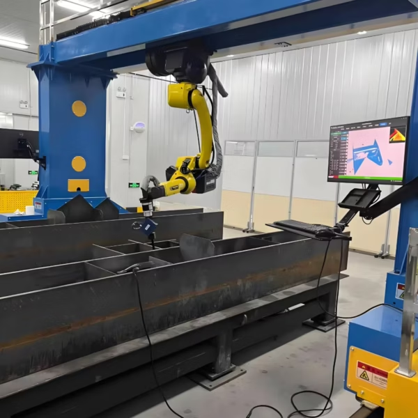
In the context of Busan’s “Smart Factory” initiatives, the Robotic Arm Welder is no longer a standalone tool but a node within a larger Industrial Automation ecosystem. During the field tests, we focused on the communication between the Robot Controller (RC) and the Master PLC (Programmable Logic Controller) via EtherCAT protocols.
2.1. Real-time Path Correction
One of the primary advantages observed was the integration of laser seam tracking sensors. For Thin Metal Sheet welding, even a 0.2mm deviation in the join line can result in a “missed” weld or excessive burn-through. By utilizing the Industrial Automation backbone, we enabled the Robotic Arm Welder to adjust its tool center point (TCP) in real-time at a 10ms sampling rate. This ensures that the 1000W energy density is focused precisely on the interface, regardless of minor jigging variations common in high-volume Busan workshops.
2.2. Automated Fixturing and Throughput
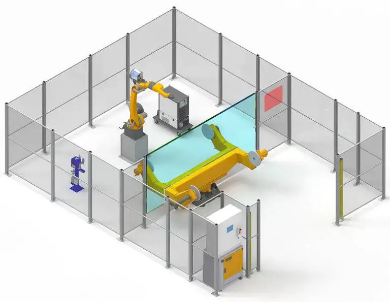
The automation suite controls a dual-station rotary indexer. This allows the operator (or a secondary loading robot) to clear finished parts while the Robotic Arm Welder maintains a duty cycle of nearly 85%. In Busan’s competitive manufacturing landscape, reducing idle time is critical. We observed that the transition from manual jigging to automated pneumatic clamping reduced part-to-part variation by 14%, directly impacting the success rate of the subsequent laser weld.
3. Technical Deep-Dive: Thin Metal Sheet Welding Challenges
The core technical hurdle in this application is managing the Heat Affected Zone (HAZ). When dealing with Thin Metal Sheet welding, the margin for error regarding thermal expansion and “oil-canning” (warpage) is nearly zero. A 1000W source, while lower in power than heavy-plate oscillators, still provides an immense power density that can easily vaporize 0.8mm substrate if travel speeds are not perfectly synchronized with the laser’s modulation.
3.1. Parameter Optimization for STS304
During the Busan field trials, we established a “Sweet Spot” matrix for 1.0mm Stainless Steel (STS304):
- Laser Power: 850W (Continuous)
- Travel Speed: 35mm/s
- Wobble Frequency: 150Hz (Circular pattern, 1.2mm width)
- Shielding Gas: Pure Argon at 15L/min
By using the “Wobble” function—a feature integrated into the Robotic Arm Welder head—we effectively increased the weld pool width without increasing the heat input to the point of structural compromise. This is vital for Industrial Automation lines where slight gaps between sheets are inevitable.
3.2. Managing Reflectivity in AL5052
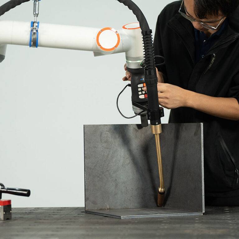
Welding aluminum sheets (1.2mm) presented the risk of back-reflection, which can damage the fiber optics. We implemented a 5-degree lead angle on the Robotic Arm Welder head to ensure reflected energy did not re-enter the delivery fiber. The Industrial Automation system was programmed to monitor the back-reflection sensors and initiate an emergency stop (E-Stop) within 2ms of a threshold breach, protecting the $40,000 laser source.
4. Lessons Learned: Environmental and Technical Constraints
Fieldwork in Busan during the humid season highlighted several factors that often go unmentioned in laboratory settings. These “lessons learned” are critical for any engineer deploying Industrial Automation in coastal regions.
4.1. Gas Purity and Porosity
We initially observed intermittent porosity in the Thin Metal Sheet welding samples. Investigation revealed that the high ambient humidity in the Busan facility was causing condensation in the shielding gas lines during overnight shifts.
Lesson Learned: We installed inline desiccant dryers and switched to high-purity (99.999%) Argon. Furthermore, we programmed the Robotic Arm Welder to perform a 2-second “pre-purge” of gas before the first arc-on command of the day. Porosity dropped to <0.5% after these changes.
4.2. Jigging Rigidity vs. Thermal Expansion
In Industrial Automation, the tendency is to clamp parts as tightly as possible. However, with Thin Metal Sheet welding, the metal needs room to expand laterally. Over-clamping led to internal stresses that caused the sheets to “pop” or buckle mid-weld.
Lesson Learned: We redesigned the copper backing bars to include a 0.5mm relief channel and adjusted the pneumatic pressure of the clamps. This allowed for thermal expansion while maintaining enough heat-sinking capability to prevent burn-through.
4.3. Robot Path Singularity
The Robotic Arm Welder experienced a “singularity” (mechanical lock-up) when attempting a complex circular weld on a cylindrical housing. This stalled the Industrial Automation line for 20 minutes.
Lesson Learned: Path planning must be reviewed in a 3D simulation environment (like RoboGuide or MotoSim) before deployment. We re-oriented the workpiece at a 15-degree tilt on the fixture to keep the robot’s 5th axis within its optimal range, eliminating the singularity risk.
5. Impact on the Busan Workshop Operations
The introduction of the 1000W Robotic Arm Welder has fundamentally shifted the facility’s production capabilities. Previously, Thin Metal Sheet welding was performed by TIG (Tungsten Inert Gas) operators. While skilled, the manual process resulted in a 12% scrap rate due to distortion and inconsistent penetration.
5.1. Quality and Consistency Metrics
Post-integration metrics show a scrap rate reduction to 1.5%. The Industrial Automation system logs every weld’s parameters (power, speed, gas flow). This data-driven approach allows the Busan plant to provide “Digital Birth Certificates” for their automotive clients, proving that every Thin Metal Sheet welding joint meets the required tensile strength specifications.
5.2. Speed and Scalability
The cycle time for a standard battery tray assembly was reduced from 4 minutes (manual) to 45 seconds (robotic). This 5.3x increase in throughput allowed the facility to take on two additional contracts without expanding their physical footprint. The Robotic Arm Welder proved that even a modest 1000W system, when properly integrated into an Industrial Automation framework, can outperform higher-powered manual setups through sheer consistency and optimized pathing.
6. Conclusion and Future Recommendations
The Busan field deployment confirms that the 1000W Robotic Arm Welder is the ideal tool for Thin Metal Sheet welding, provided that the Industrial Automation environment is robust enough to handle high-speed feedback loops. The precision of the 6-axis movement, combined with modern fiber laser stability, solves the historical “warpage” problem that has plagued thin-gauge fabrication.
For future phases, I recommend the integration of AI-based vision inspection at the end of the line. Currently, the Industrial Automation system handles the “doing,” but the “checking” is still a manual QC process. By installing a high-resolution camera on the robot’s 7th axis or a fixed gantry, the Busan facility can achieve a fully closed-loop manufacturing cycle.
Senior Engineer’s Note: Always check the chillers in Busan. The salt air is corrosive. Ensure the heat exchangers are cleaned monthly to prevent the 1000W source from overheating during the summer months.