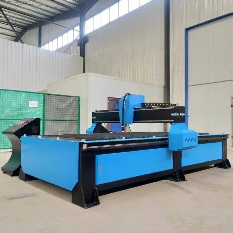
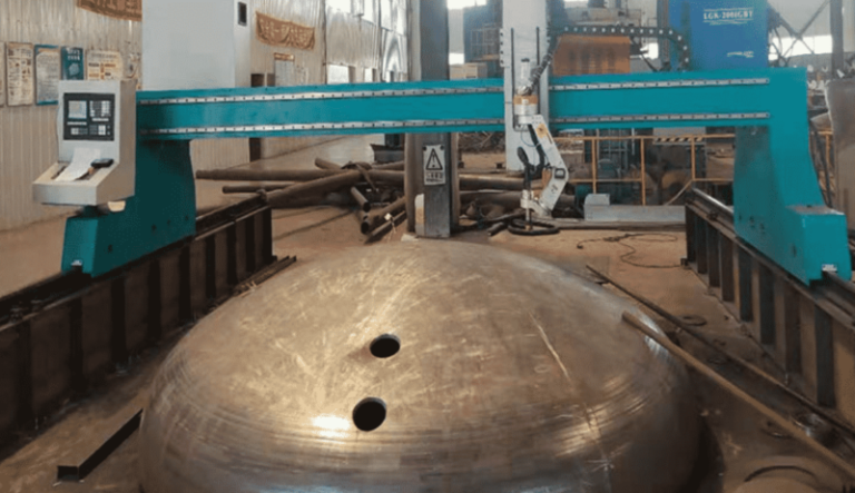
H-Beam Production Line with Narrow Gap welding for Oil & Gas Tanks
In this article
- Technical Optimization of H-Beam Fabrication for Oil and Gas Infrastructure
- The Criticality of Intersection Accuracy in Heavy Structural Sections
- Advanced Plasma Beveling for Narrow Gap Preparation
- Operational Efficiency and Low Maintenance Design
- Integration with Automated Production Workflows
- Conclusion: The Strategic Choice for Tank Fabrication
Technical Optimization of H-Beam Fabrication for Oil and Gas Infrastructure
The structural requirements for Oil and Gas storage tanks necessitate H-beams that can withstand extreme hydrostatic loads and environmental stressors. In a modern H-beam production line, the initial cutting and shaping phase dictates the success of subsequent joining processes. For facilities utilizing narrow gap welding, the margin for error in fit-up is virtually non-existent. This report focuses on the deployment of high-definition Plasma Cutting systems as the primary method for ensuring the geometric precision and edge quality required for these high-stakes applications.
The Criticality of Intersection Accuracy in Heavy Structural Sections
In the context of tank farm construction, H-beams often serve as the primary radial rafters or support columns. These components frequently require complex intersections where beams meet at non-perpendicular angles. Achieving high intersection accuracy is not merely a matter of aesthetic fit; it is a fundamental requirement for load distribution. When a plasma system is integrated into a multi-axis robotic gantry, it can execute copes, miters, and notches with a tolerance of +/- 0.5mm.
From an industrial engineering perspective, this precision reduces the need for secondary filling or manual grinding. In narrow gap welding, the groove geometry must be consistent throughout the entire length of the joint. If the plasma cut deviates, the automated welding head may encounter variations in the root opening, leading to lack of fusion or excessive burn-through. By utilizing sophisticated CNC compensation algorithms, plasma systems can account for beam camber and sweep, ensuring that every intersection is mathematically perfect relative to the actual workpiece dimensions rather than just the theoretical CAD model.
Thermal Management and Material Integrity
High-definition plasma cutting utilizes a constricted arc to concentrate heat into a very narrow area. This is particularly important for the high-strength steels used in the Oil and Gas industry. By maximizing cutting speed and optimizing the gas swirl, the heat-affected zone (HAZ) is minimized. A smaller HAZ ensures that the metallurgical properties of the H-beam—such as yield strength and ductility—remain intact near the weld preparation zone. This is a vital consideration for tanks that will store volatile or corrosive substances, where localized material softening could lead to premature structural failure.
Advanced Plasma Beveling for Narrow Gap Preparation
Traditional welding preparation often involves wide V-grooves that require multiple passes and significant amounts of filler metal. Narrow gap techniques, however, utilize a much tighter groove angle, typically between 1 and 5 degrees. The success of this efficiency-boosting method depends entirely on the capability of the plasma beveling system.
Multi-Pass Beveling vs. Single-Pass Execution
Modern plasma units equipped with tilt-and-rotate torches can execute complex bevel profiles (V, X, Y, or K joints) in a single pass. For H-beams used in tank supports, the flange thickness can often exceed 25mm. Plasma technology excels in this thickness range, maintaining a stable arc that produces a clean, dross-free surface. The ability to cut a bevel directly onto the flange or web of an H-beam while it is on the production line eliminates the need for transporting the component to a separate beveling station, thereby reducing material handling costs and cycle times.
Furthermore, the angular accuracy of the plasma head is controlled by high-resolution encoders. In a narrow gap welding workflow, even a one-degree deviation in the bevel angle can significantly increase the volume of the weld pool, negating the cost benefits of the narrow gap process. Therefore, the integration of real-time torch height control (THC) is essential. THC ensures the torch maintains a constant distance from the material surface, compensating for any slight irregularities in the beam’s surface and maintaining the integrity of the bevel angle throughout the entire cut.
Operational Efficiency and Low Maintenance Design
In a high-throughput industrial environment, downtime is the primary enemy of profitability. One of the most significant advantages of plasma systems in an H-beam line is their robust, low-maintenance nature. Unlike other thermal cutting processes that involve sensitive optics or complex gas mixing chambers, plasma systems are built for the grit and vibration of a structural steel shop.
Consumable Life and System Reliability
The evolution of electrode and nozzle design has dramatically extended the life of plasma consumables. Modern systems utilize “coolant-on-tip” technology, which effectively manages the thermal load on the torch components. For an industrial engineer, this translates to fewer mid-shift interventions and a higher duty cycle. In the Oil and Gas sector, where production schedules are often dictated by rigid project timelines, the reliability of the H-beam production line is paramount.
Maintenance protocols for plasma systems are straightforward, typically involving the periodic replacement of wear parts and the inspection of gas filtration systems. Because plasma systems do not require the ultra-clean environments demanded by more sensitive technologies, they can be positioned directly adjacent to heavy fabrication activities. This ruggedness ensures that the intersection accuracy remains consistent over months of double-shift operations without requiring frequent recalibration of the motion system.
Integration with Automated Production Workflows
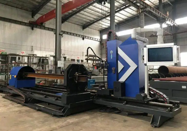
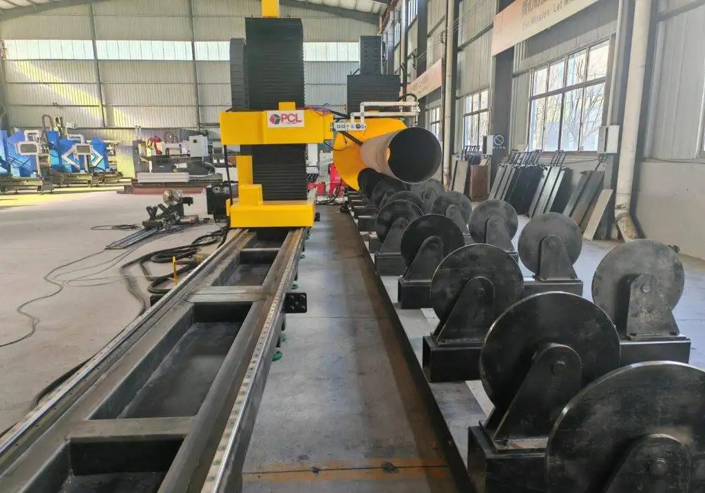
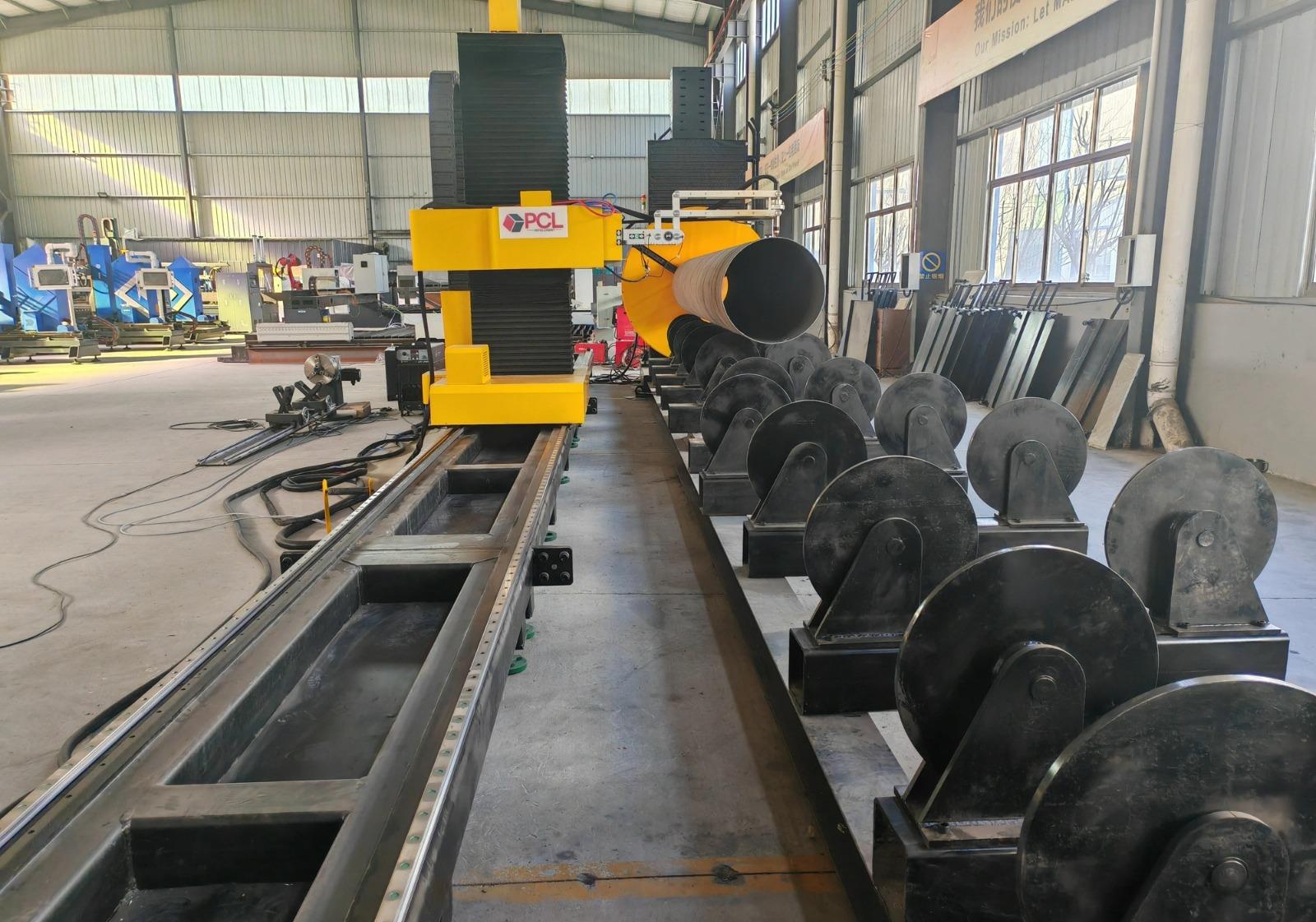
The synergy between plasma cutting and narrow gap welding represents the pinnacle of modern structural engineering. The process begins with the raw H-beam entering the line, where it is scanned for dimensional variances. The plasma system then receives the cutting path instructions, executing all necessary holes, cope cuts, and bevels.
The clean, oxide-free edges produced by high-definition plasma are essentially “weld-ready.” For narrow gap welding, surface tension and arc stability are sensitive to contaminants. The use of specific plasma gas mixtures, such as Oxygen for carbon steel or H35 (an Argon-Hydrogen blend) for stainless steel components in specialized gas tanks, ensures that the cut edge does not introduce impurities into the weld pool. This seamless transition from the cutting gantry to the welding station is what allows for the rapid assembly of massive tank structures with minimal manual labor.
Economic Impact of Precision Cutting
By investing in high-end plasma capabilities, a fabrication facility can see a drastic reduction in total cost per ton. The savings are realized in three areas:
1. Reduction in filler metal consumption due to precise narrow gap welding preparation.
2. Elimination of secondary processing through superior intersection accuracy.
3. Lowered overhead through a low maintenance equipment profile that keeps the line moving.
Conclusion: The Strategic Choice for Tank Fabrication
For the Oil and Gas industry, the structural integrity of H-beam supports is a non-negotiable safety requirement. Plasma cutting technology provides the necessary balance of speed, thickness capacity, and precision to meet these demands. By focusing on the mechanical advantages of plasma beveling and the operational benefits of a rugged, low-maintenance system, engineers can design production lines that are not only efficient but also capable of producing the highest quality structural components. The transition to narrow gap welding, supported by the foundational accuracy of plasma cutting, represents the future of large-scale industrial fabrication.