H-Beam Production Line with Offline Programming for LNG Projects
In this article
Engineering H-Beam Integrity for LNG Infrastructure
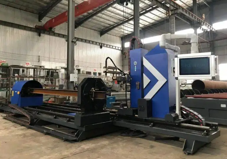
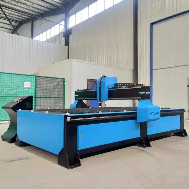
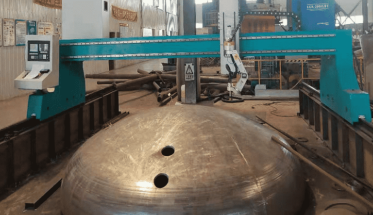
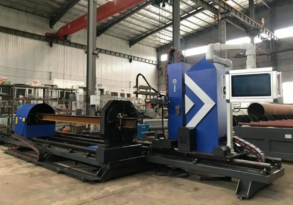
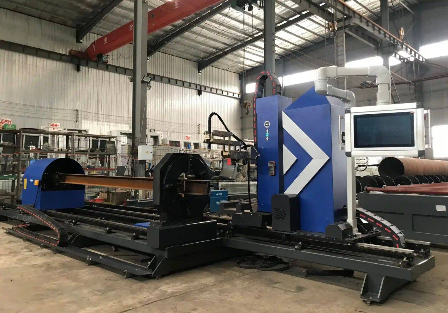
The construction of Liquefied Natural Gas (LNG) terminals and processing facilities demands an unprecedented level of structural reliability. Given the volatile nature of the medium and the cryogenic temperatures involved, the H-beams used in these projects must meet stringent tolerances. The pivot toward High-Definition Plasma Cutting in modern production lines is driven by the need to process heavy-gauge structural steel with speed and geometric precision. Unlike traditional methods, plasma systems designed for H-beams integrate multi-axis robotic arms that allow for the processing of all four sides of a profile in a single pass, significantly reducing material handling.
Industrial engineers overseeing LNG projects prioritize the reduction of “fit-up” time. In large-scale structural frames, even a minor deviation in an H-beam cut can lead to cumulative errors, resulting in costly on-site modifications. By utilizing high-density thermal energy, plasma systems achieve clean, square cuts that facilitate immediate assembly. This level of output is essential when managing the thousands of tons of steel typical of modular LNG liquefaction trains.
The Role of Offline Programming in Complex Fabrication
One of the most significant bottlenecks in H-beam production is the manual teaching of robotic paths. In the context of LNG projects, where beam geometries vary across the pipe rack and support structures, manual programming is inefficient. Offline Programming (OLP) bridges the gap between the design office and the factory floor. By importing 3D CAD models directly into the OLP environment, engineers can generate cutting paths, simulate torch movements, and perform collision detection before the steel ever reaches the conveyor.
OLP software utilizes sophisticated nesting algorithms to maximize material yield, which is critical given the high cost of the specialized alloys often used in energy infrastructure. This digital workflow ensures that the robot’s kinematics are optimized for the specific dimensions of the H-beam, including compensation for flange thickness variations. The result is a seamless transition from architectural design to physical component, eliminating the downtime associated with “point-to-point” manual teaching.
Maximizing Intersection Accuracy for Structural Stability
The structural complexity of LNG modules requires intricate intersections where H-beams meet at various angles and planes. Achieving high Intersection Accuracy is not merely a matter of aesthetics; it is a requirement for load distribution and seismic resilience. Plasma cutting robots, guided by OLP, execute precise cope cuts, blocks, and notches that allow for perfect interlocking of beams.
The precision of the plasma arc, combined with real-time laser measurement systems, allows the production line to account for the inherent “mill tolerance” deviations in hot-rolled steel. Before the cut begins, the system probes the beam to determine its actual height and width, adjusting the OLP-generated path to ensure the intersection point is mathematically perfect. This compensates for web off-center or flange tilt, ensuring that when the H-beams arrive at the assembly site, they lock together with minimal gap, facilitating superior weld quality.
Advanced Beveling for High-Performance Welding
Welding for LNG Projects often involves Full Penetration (FP) welds to handle the thermal expansion and contraction cycles of cryogenic environments. This necessitates complex beveling on both the web and the flanges of the H-beam. Modern plasma cutting heads are equipped with 5-axis or 6-axis movement capabilities, enabling them to produce V, Y, X, and K bevels in a single operation.
The ability to bevel the thick flanges of an H-beam at variable angles is a core advantage of plasma technology. Because the plasma arc can be manipulated with high angular velocity, the system can transition from a straight cut to a 45-degree bevel without pausing. This maintains a consistent Heat Affected Zone (HAZ) and prevents the distortion of the steel. For the industrial engineer, this means the H-beam leaves the production line ready for the welding station with no secondary grinding required to fix edge geometry.
H-Beam Low Maintenance and Operational Continuity
In the high-throughput environment of an LNG project, equipment downtime can derail the entire construction schedule. A primary benefit of plasma-based H-Beam Fabrication lines is their inherent mechanical robustness. Plasma systems are designed for “dirty” industrial environments where dust, vibration, and temperature fluctuations are common. The consumables—nozzles, electrodes, and swirl rings—are designed for rapid replacement, often requiring less than two minutes of downtime.
Furthermore, the lack of complex optical paths or sensitive alignment requirements makes plasma systems far more resilient to the physical shocks of loading and unloading 12-meter H-beams. The maintenance schedule for a plasma power source and robotic arm is predictable and straightforward, focusing on cooling systems and cable management. This reliability ensures that the production line can operate on a 24/7 basis, meeting the aggressive timelines often found in the oil and gas sector.
Thermal Efficiency and Material Integrity
Managing the heat input during the cutting process is vital for maintaining the metallurgical properties of the H-beam. High-definition plasma systems use constricted arcs and secondary shielding gases to focus the energy into a very narrow kerf. This minimizes the heat transferred to the surrounding metal, preserving the tensile strength and ductility of the steel—properties that are vital for the structural safety of LNG facilities.
By integrating sensors that monitor gas flow and arc voltage, the system maintains a consistent cut quality across the entire length of the H-beam. The combination of OLP path optimization and plasma’s high cutting speeds ensures that the material spends the least amount of time possible under thermal stress. This balance of speed, precision, and durability defines the modern approach to heavy structural fabrication in the energy sector.
Conclusion: Scaling Production through Automation
The synergy between High-Definition Plasma Cutting and Offline Programming represents the pinnacle of current H-beam production technology. For LNG projects, where the margin for error is non-existent, these systems provide a scalable solution that guarantees intersection accuracy and weld-ready beveling. By focusing on low-maintenance hardware and sophisticated digital twins for path planning, industrial engineers can achieve a level of throughput and quality that traditional fabrication methods cannot match. The result is a more resilient infrastructure, delivered on time and within the rigorous safety parameters of the global energy industry.