Field Report: Robotic Integration and Tool Steel Repair in Pune Automotive Cluster
1. Project Overview and Site Conditions
This report details the commissioning and optimization of a 2000W-equivalent high-precision robotic cell at a Tier-1 automotive tooling facility in Chakan, Pune. The primary objective was to transition from manual GTAW (TIG) to an automated system capable of handling high-volume cladding and repair. Specifically, we focused on the deployment of a MIG/MAG Welding Robot to execute complex Tool Steel welding on injection mold inserts and forging dies.
Pune’s industrial environment presents unique challenges. During the monsoon transition, ambient humidity in the workshop peaked at 85%, necessitating stringent control over shielding gas dew points and wire storage protocols. Furthermore, the local power grid stability required the installation of dedicated active power filtering to ensure the Arc Welding Solutions software maintained consistent arc length feedback loops without signal noise interference.
2. Hardware Configuration: The MIG/MAG Welding Robot
The core of the installation is a 6-axis industrial arm integrated with a 2000W-class high-speed inverter power source. Unlike standard structural steel setups, a MIG/MAG Welding Robot tasked with tool-grade alloys requires a high-fidelity wire drive system. We utilized a push-pull torch configuration to ensure zero-stutter delivery of specialized 1.2mm maraging steel and H13-equivalent wires.
Synergy of Motion and Power
The integration of the robot with our proprietary Arc Welding Solutions allowed for “Through-Arc Seam Tracking” (TAST). In the Pune facility, we found that cast tool bases often had dimensional variances of ±1.5mm. Manual intervention would have slowed cycle times by 40%. The robot’s ability to adjust the tool center point (TCP) in real-time while maintaining a constant stick-out was the difference between a successful fusion and a cold-lap defect.
3. Implementing Advanced Arc Welding Solutions
In the context of high-end tool manufacturing, “Arc Welding Solutions” is not just a marketing term; it refers to the digital twin synchronization and the waveform modulation used to control the heat-affected zone (HAZ). We implemented a pulsed-spray transfer mode to minimize spatter—a critical requirement for Tool Steel welding where post-weld machining costs are exorbitant.
Waveform Optimization
We customized the pulse profile to include a sharp current peak followed by a controlled ramp-down. This specific arc geometry ensures deep penetration into the tool steel base while keeping the average heat input low enough to prevent the formation of excessive primary martensite in the coarse-grained HAZ. In our Pune trials, this reduced the necessity for extreme pre-heating, allowing us to work at a manageable 250°C instead of the traditional 400°C.
4. Technical Deep-Dive: Tool Steel Welding Challenges
Tool Steel welding is notoriously unforgiving due to the high carbon and alloy content (Chromium, Molybdenum, Vanadium). The primary risk is Hydrogen Induced Cold Cracking (HICC). In the Pune workshop, we identified that the interaction between the MIG/MAG Welding Robot‘s speed and the cooling rate of the tool steel needed precise calibration.
Metallurgical Control and Preheat Protocols
We utilized induction heating coils synchronized with the robot’s PLC. Before the MIG/MAG Welding Robot initiated the arc, the Arc Welding Solutions software verified the surface temperature via infrared sensors. For H13 tool steel inserts, we maintained an interpass temperature of 300°C. The robot was programmed with a “stringer bead” technique rather than a “weave bead” to minimize the dwell time of the arc over any single point, thereby refining the grain structure of the weld metal.
Gas Composition and Shielding
To combat the Pune humidity, we shifted from a standard 80/20 Argon-CO2 mix to a triple-mix (Ar/CO2/O2) with a high-purity (99.999%) Argon base. This stabilized the arc plasma column, reducing the “arc wandering” often seen when robotic systems encounter the magnetic fields inherent in large tool steel blocks.
5. Real-World Synergy: Case Study in the Pune Workshop
The true value of the MIG/MAG Welding Robot was realized during the repair of a 1.5-ton plastic injection mold. Traditionally, this tool would be sent for manual TIG welding, taking 48 hours for prep, weld, and stress relief.
By deploying our automated Arc Welding Solutions, we mapped the worn edges of the die using the robot’s touch-sensing capabilities. The Tool Steel welding phase, which involved building up a 5mm worn edge with H13 filler, was completed in 4 hours. The consistency of the robotic bead meant that the CNC finishing team removed 60% less “over-weld” material than they would have with a manual weld. This synergy between hardware precision and metallurgical software reduced the total downtime of the Pune production line by three full days.
6. Lessons Learned and Engineering Best Practices
Fieldwork in the Indian manufacturing sector provides hard data that laboratory tests often miss. Below are the key engineering takeaways from this deployment:
The “Dust Factor” in Robotic Maintenance
Pune’s industrial zones have high particulate matter. We found that the wire liners of the MIG/MAG Welding Robot were clogging every 72 hours of operation. Lesson: Standard plastic liners are insufficient. We transitioned to ceramic-coated liners and implemented an automated compressed-air blow-back system every 10 cycles. This is a critical component of Arc Welding Solutions that is often overlooked in cleaner European or Japanese environments.
Thermal Drift and TCP Calibration
When performing Tool Steel welding, the heat radiation from the preheated workpiece (300°C+) causes thermal expansion in the robot’s 6th axis arm. We observed a TCP drift of 0.8mm over a two-hour shift. To counteract this, we programmed a mandatory “re-calibration touch-off” every 30 minutes. In high-precision tooling, a 0.8mm deviation is the difference between a repair and a scrap component.
Earthing and HF Interference
One specific Pune-site issue was the “floating earth” in older workshop bays. The high-frequency components of the Arc Welding Solutions power source were feeding back into the robot’s encoders, causing erratic movement. We solved this by installing a dedicated 3-meter copper earth pit for the welding cell, independent of the factory mains. This stabilized the arc characteristics immediately.
7. Conclusion
The deployment of the MIG/MAG Welding Robot at the Pune site demonstrates that automation is no longer just for thin-sheet automotive body-in-white applications. When integrated with sophisticated Arc Welding Solutions, these robots can handle the thermal and metallurgical complexities of Tool Steel welding with higher repeatability than manual operators.
For future installations in the Maharashtra region, the focus must remain on environmental hardening—addressing humidity, dust, and power quality—while leveraging the robot’s data-logging capabilities to provide a digital birth certificate for every tool repaired. The transition from manual “artisan” welding to robotic “precision” welding is the key to scaling Pune’s die and mold industry to global standards.
Report Prepared By: Senior Welding Engineer, Site Services Division
Location: Chakan Industrial Area, Pune, India
Status: Commissioning Complete / Production Steady-State
-


LT240S tube laser cutting machine
-
LT120S tube laser cutting machine
-
Sale

Tank Fillet Welding Machine
Original price was: $1,000.00.$900.00Current price is: $900.00. -
Sale

MAK100 tube laser cutting machine
Original price was: $5,500.00.$5,000.00Current price is: $5,000.00. -

portable plasma air cutting machine
$1,200.00 -

2in1 fiber laser cutting machine
-

Air cooling Laser welding machine
-

HF h beam laser cutting machine
-

LT240 laser cutting machine
-

Laser welding machine
-


Cobot Welding Station
-

Gantry welding robot solution
-

Tracked Wheeled AGV Welding robot
-

LFH6020 Fiber laser cutting machine
-
LFP6020
-

robotic welidng machine
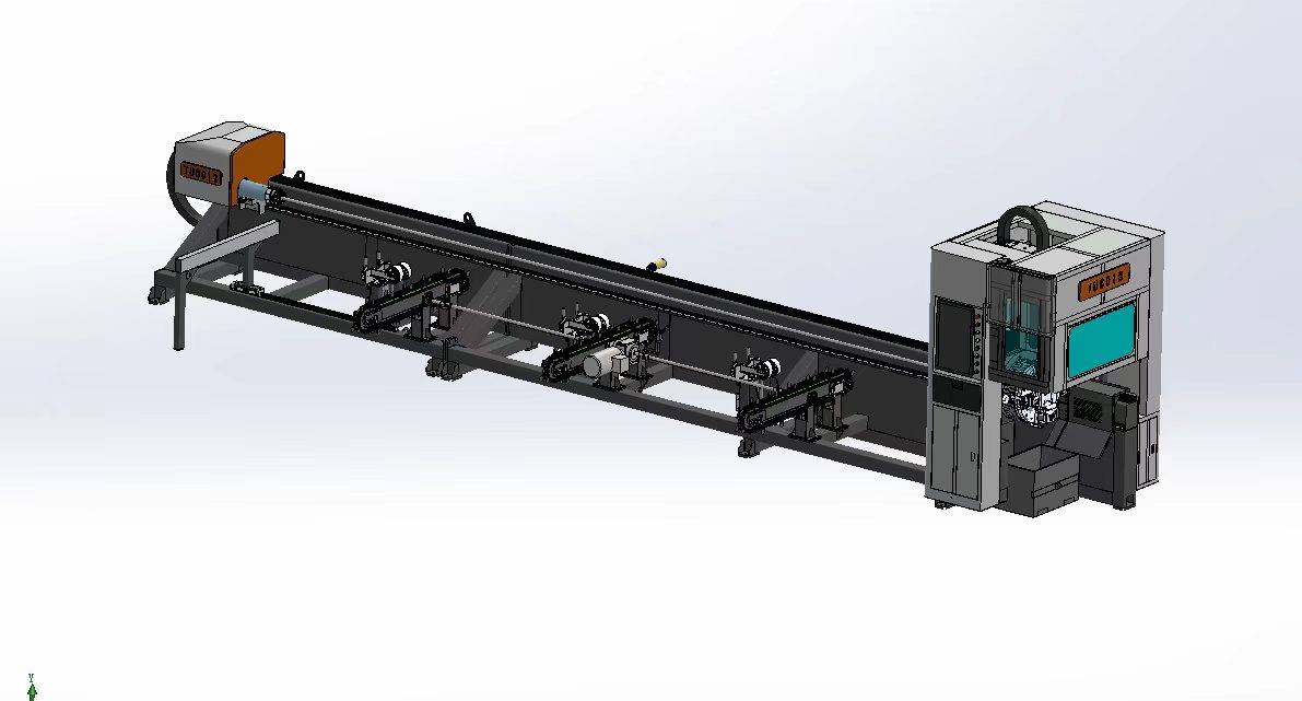
Advanced Fiber Laser Tube Processing Technology
Our CNC Fiber Laser Tube Cutting systems revolutionize metal fabrication by integrating high-precision cutting, punching, and profiling into a single automated workflow. Designed for versatility, this technology handles a wide array of profiles including Round, Square, Rectangular, and Oval tubes, as well as complex L-shaped and U-shaped channels.
- Precision Punching: High-speed hole punching with micron-level accuracy, eliminating the need for mechanical drilling or die-stamping.
- Complex Profiling: Advanced 3D pathing allows for intricate interlocking joints and specialized notch cuts, ideal for structural frames.
- High Material Efficiency: Intelligent nesting software minimizes scrap, reducing raw material costs across large production runs.
- Clean Finish: Delivers oxide-free, burr-free edges that require zero secondary grinding before welding.

Seamlessly processing multiple profiles with consistent precision.
Global Delivery & Logistics


From our high-tech manufacturing facility directly to your global site. PCL WeldCut ensures secure packaging, professional handling, and reliable international logistics to safeguard your equipment throughout the entire journey.