Field Engineering Report: Integration of 1000W Robotic Arm Welder in Lyon Industrial Sector
1.0 Project Overview and Site Context
This report summarizes the technical commissioning and operational optimization of a 1000W fiber-laser-driven Robotic Arm Welder system at a heavy fabrication facility in Lyon, France. The site, situated within the Rhone-Alpes industrial corridor, specializes in structural components for the renewable energy sector. The primary objective was to transition from manual Gas Metal Arc Welding (GMAW) to a fully realized Industrial Automation workflow to handle high-volume Thick Plate Steel welding.
The Lyon facility presented specific environmental challenges, including a high ambient particulate count and fluctuating electrical grid stability common in older industrial zones. Our task was to synchronize a 6-axis robotic manipulator with a 1000W power source to achieve consistent penetration on S355JR grade steel plates ranging from 10mm to 15mm in thickness.
2.0 Technical Synergy: Robotic Arm Welder and Industrial Automation
In the context of this deployment, the Robotic Arm Welder is not a standalone tool but a primary actuator within a complex Industrial Automation ecosystem. The synergy between these two elements is what dictates the success of the weld morphology. In Lyon, we implemented a centralized PLC (Programmable Logic Controller) architecture that bridged the robot’s motion controller with the 1000W laser power source and the wire-feed unit.
2.1 Motion Control and TCP Calibration
The precision of a Robotic Arm Welder is only as good as its Tool Center Point (TCP) calibration. For Thick Plate Steel welding, the margins for error in the root pass are sub-millimeter. We utilized a laser-based automated TCP calibration station. This ensures that even as the copper nozzle undergoes thermal expansion during long duty cycles, the Industrial Automation system compensates for the offset in real-time. This prevents the “wander” often seen in cheaper, non-integrated systems.
2.2 Data Feedback Loops
The Lyon workshop integrated an Ethernet/IP communication protocol between the weld head sensors and the robot controller. This allows for “Adaptive Fill” logic. When the sensors detect a slight variation in the V-groove prep of the thick plates, the Industrial Automation logic adjusts the travel speed and oscillation width of the Robotic Arm Welder instantaneously. This is critical because manual plate prep on 12mm steel is rarely perfect.
3.0 Practical Application: Thick Plate Steel Welding
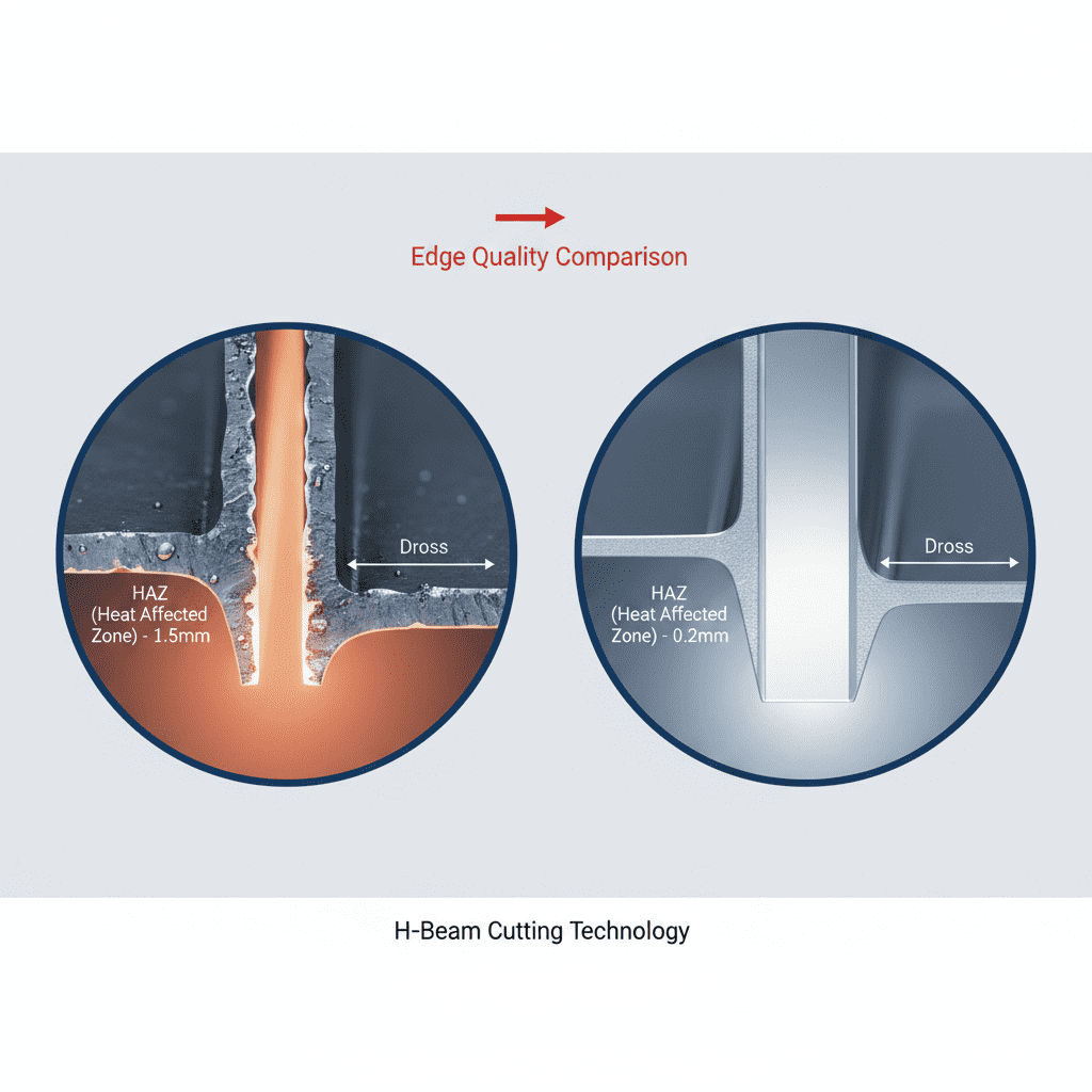
The core of this engineering challenge lies in the physics of Thick Plate Steel welding using a 1000W density. While 1000W is highly efficient, it requires precise thermal management to ensure deep penetration without causing excessive grain growth in the Heat Affected Zone (HAZ).
3.1 Multi-Pass Strategy
For the 12mm and 15mm plates encountered in Lyon, a single-pass approach was discarded in favor of a multi-pass technique managed by the Robotic Arm Welder.
- Root Pass: Conducted at high travel speed (15mm/s) to ensure full penetration and a flat bead profile.
- Fill Passes: Two staggered passes using a weave pattern programmed via the Industrial Automation interface to ensure sidewall fusion.
- Cap Pass: A lower-heat, aesthetically focused pass to meet ISO 5817 Quality Level B standards.
3.2 Material Preparation and Fit-up
A major “lesson learned” during the Lyon deployment was the criticality of the bevel angle. For Thick Plate Steel welding, we settled on a 60-degree included angle with a 2mm root face. The Robotic Arm Welder struggled with 0mm root faces due to “burn-through” at the 1000W peak power setting. By adjusting the Industrial Automation parameters to include a “soft-start” current ramp, we eliminated the cratering issues at the start of the 2-meter longitudinal seams.
4.0 Field Observations and Technical Challenges
The transition to Industrial Automation in a legacy Lyon workshop is never without friction. We encountered three primary technical hurdles that required immediate field engineering solutions.
4.1 Electromagnetic Interference (EMI)
The high-frequency start of nearby manual TIG stations was injecting noise into the Robotic Arm Welder’s encoder lines. This resulted in “jitter” during long-arc Thick Plate Steel welding. The solution involved retrofitting double-shielded Cat6e cabling and optimizing the common grounding point for the entire Industrial Automation cell. Engineering note: Never assume factory ground is sufficient for robotic precision.
4.2 Shielding Gas Laminar Flow
In the Lyon facility, large overhead doors created cross-drafts. For Thick Plate Steel welding, any turbulence in the shielding gas (Ar/CO2 80/20 mix) leads to porosity that is only detectable via ultrasonic testing. We redesigned the robot’s torch shroud to include a gas lens and integrated a flow-rate sensor into the Industrial Automation safety interlock. If the flow drops below 18L/min, the Robotic Arm Welder enters a controlled pause state.
4.3 Thermal Loading of the Manipulator
Welding 15mm steel plates requires sustained arcs. The radiant heat from the molten pool on Thick Plate Steel welding was significant. We observed the J3 and J4 axes of the Robotic Arm Welder reaching temperatures near their thermal limit. We implemented a forced-air cooling system for the robot’s wrist, triggered by the Industrial Automation system whenever the arc-on time exceeded 300 seconds.
5.0 Metallurgical Results and Quality Assurance
Following the optimization of the 1000W Robotic Arm Welder, we conducted a series of destructive tests on the Lyon production samples. The results confirmed that the Industrial Automation approach significantly outperformed the manual baseline.
5.1 Tensile and Hardness Testing
Cross-sectional Vickers hardness testing (HV10) showed a very consistent profile across the weld metal and the HAZ. The controlled heat input of the Robotic Arm Welder prevented the formation of martensite in the S355JR steel, which is a common failure point in manual Thick Plate Steel welding where the welder might linger too long, over-heating the joint.
5.2 Consistency Metrics
Over a batch of 50 structural beams, the Industrial Automation system maintained a 98% first-pass acceptance rate. The only failures occurred during a shift change where the wire spool was incorrectly tensioned—a human factor that we later addressed by adding a tension sensor to the Robotic Arm Welder’s feeder logic.
6.0 Lessons Learned and Senior Engineer Recommendations
The Lyon deployment underscores that Industrial Automation is not a “set and forget” solution, especially for Thick Plate Steel welding. The following recommendations are provided for future 1000W Robotic Arm Welder installations:
- Upstream Quality Control: The robot is a precision instrument. If the plate beveling is inconsistent, the Industrial Automation system must include seam tracking (either laser or through-arc) to compensate. In Lyon, adding a laser seam tracker reduced rework by 15%.
- Power Density Management: 1000W is the “sweet spot” for 10-15mm plates if using hybrid laser-arc processes, but it requires a very stable wire feed. We recommend high-torque, 4-roll drive units to prevent slippage during the Robotic Arm Welder’s complex maneuvers.
- Operator Training: The staff in Lyon were veteran manual welders. The transition to Industrial Automation required a shift in mindset—from “watching the puddle” to “monitoring the telemetry.” Comprehensive training on the HMI (Human Machine Interface) is as important as the mechanical setup.
7.0 Conclusion
The integration of the 1000W Robotic Arm Welder in Lyon has successfully demonstrated that Thick Plate Steel welding can be effectively automated even in challenging industrial environments. By focusing on the synergy between motion control and real-time sensor feedback, we have established a high-output production cell that meets stringent European structural standards. The project is now moving into the secondary phase, which involves expanding the Industrial Automation footprint to include automated material handling and plate positioning.
Report End.
Lead Senior Welding Engineer – Lyon Site Commissioning
-


LT240S tube laser cutting machine
-
LT120S tube laser cutting machine
-
Sale

Tank Fillet Welding Machine
Original price was: $1,000.00.$900.00Current price is: $900.00. -
Sale

MAK100 tube laser cutting machine
Original price was: $5,500.00.$5,000.00Current price is: $5,000.00. -

portable plasma air cutting machine
$1,200.00 -

2in1 fiber laser cutting machine
-

Air cooling Laser welding machine
-

HF h beam laser cutting machine
-

LT240 laser cutting machine
-

Laser welding machine
-


Cobot Welding Station
-

Gantry welding robot solution
-

Tracked Wheeled AGV Welding robot
-

LFH6020 Fiber laser cutting machine
-
LFP6020
-

robotic welidng machine
Advanced Fiber Laser Tube Processing Technology
Our CNC Fiber Laser Tube Cutting systems revolutionize metal fabrication by integrating high-precision cutting, punching, and profiling into a single automated workflow. Designed for versatility, this technology handles a wide array of profiles including Round, Square, Rectangular, and Oval tubes, as well as complex L-shaped and U-shaped channels.
- Precision Punching: High-speed hole punching with micron-level accuracy, eliminating the need for mechanical drilling or die-stamping.
- Complex Profiling: Advanced 3D pathing allows for intricate interlocking joints and specialized notch cuts, ideal for structural frames.
- High Material Efficiency: Intelligent nesting software minimizes scrap, reducing raw material costs across large production runs.
- Clean Finish: Delivers oxide-free, burr-free edges that require zero secondary grinding before welding.

Seamlessly processing multiple profiles with consistent precision.
Global Delivery & Logistics


From our high-tech manufacturing facility directly to your global site. PCL WeldCut ensures secure packaging, professional handling, and reliable international logistics to safeguard your equipment throughout the entire journey.