Optimizing Material Utilization with Zero-tailing technology
In the context of Wind Tower fabrication, the cost of raw materials—specifically high-grade structural steel—represents a substantial portion of the total project expenditure. Traditional thermal cutting processes often leave significant “tails” or scrap ends on pipes and profiles because the clamping mechanisms require a minimum distance from the cutting torch to maintain stability. Zero-tailing technology redefines this workflow by utilizing a multi-chuck feeding system, typically involving three or four independent synchronous chucks.
As the workpiece progresses through the Plasma Cutting Machine, the chucks pass the material off to one another in a “hand-over-hand” sequence. This allows the cutting torch to access the very end of the profile or pipe. By eliminating the dead zone associated with standard clamping, manufacturers can achieve material utilization rates exceeding 98 percent. For wind tower internals, such as ladder supports and platform frames, this precision translates directly into lower procurement costs and reduced scrap handling logistics.
Precision Intersection Accuracy for Structural Integrity
Wind towers are subjected to extreme dynamic loads and environmental stresses. The structural integrity of the tower depends heavily on the fit-up of intersecting members, such as secondary support tubes and main shell reinforcements. Achieving high intersection accuracy is not merely a matter of aesthetic quality; it is a requirement for ensuring uniform load distribution across the welded joint.
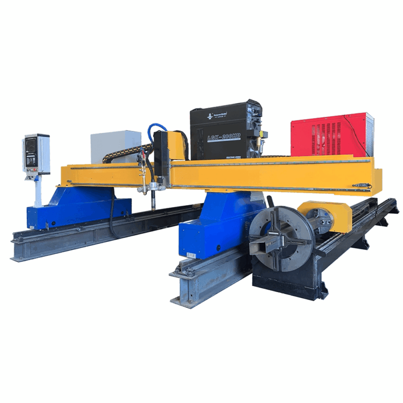
Modern plasma systems utilize advanced CNC algorithms to calculate the complex saddle and hole intersections required for these components. The software compensates for the kerf width of the plasma arc and the pipe’s ovality in real-time. By maintaining a tolerance within ±0.5mm, the machine ensures that the gap between the two intersecting parts is minimized. This level of accuracy eliminates the need for manual trimming or bridging large gaps, which are common points of failure in high-stress offshore wind environments.
Advanced Beveling for Heavy-Wall Weld Preparation
The thickness of the steel plates and profiles used in wind tower construction necessitates complex weld preparations. Single-pass Beveling accuracy is a core performance metric for industrial plasma systems. Unlike standard 2D cutting, a 5-axis or 6-axis robotic plasma head can execute V, Y, X, and K-shaped bevels in a single continuous motion.
For the thick-walled shells of a wind tower, a precise Y-bevel is often required to ensure deep penetration during the automated submerged arc welding process that follows. The plasma torch must maintain a constant standoff distance from the curved surface while varying its angle relative to the material thickness. Modern plasma power sources provide high-definition (HD) arc stability, which results in a smooth, dross-free surface on the beveled edge. This metallurgical quality reduces the requirement for post-cut grinding, thereby accelerating the overall production timeline and reducing labor costs.
Low Maintenance H-Beam Processing Strategies
Wind tower platforms and internal structures frequently utilize H-beams and I-beams for rigidity. Historically, these profiles were processed using mechanical saws and drills, which involve high consumable costs and frequent downtime for tool sharpening. Transitioning to a plasma-based H-beam processing line offers a significant reduction in maintenance overhead.
The non-contact nature of plasma cutting means there is no mechanical force exerted on the machine structure, reducing wear on bearings, rails, and motors. Furthermore, the Plasma Cutting Machine can handle web and flange cutting, bolt hole piercing, and marking in one setup. The maintenance cycle is centered almost exclusively on the replacement of copper electrodes and nozzles, which can be performed in minutes. This shift from mechanical tool management to consumable-based maintenance allows for higher machine uptime and more predictable operational budgets in high-volume wind energy fabrication facilities.
Thermal Management and Heat-Affected Zone Control
An industrial engineer must account for the Heat-Affected Zone (HAZ) when specifying cutting parameters for wind tower components. While plasma is a thermal process, high-speed plasma gas delivery and narrow-constriction nozzles concentrate the energy into a very small area. This concentration results in a localized heat input that prevents significant distortion of the workpiece.
In zero-tailing systems, where the material is supported by multiple points, the risk of thermal bowing is further mitigated. The synchronization between the motion controller and the power supply ensures that the arc intensity is modulated during cornering or when navigating tight radii. This prevents “over-burning” at the edges, preserving the mechanical properties of the steel and ensuring that the final component meets the rigorous fatigue-resistance standards required by the wind industry.
Digital Integration and Production Monitoring
The effectiveness of zero-tailing technology is maximized when integrated with high-level nesting software. The software analyzes the production queue and nests parts of varying lengths on a single raw stock piece to minimize the final remnant. In a wind tower facility, this digital thread connects the engineering design phase directly to the shop floor.
Data logging features in modern plasma systems track consumable life, gas pressures, and cutting speeds. By monitoring these variables, industrial engineers can implement predictive maintenance schedules, ensuring the machine never fails during critical production runs. The ability to export real-time “as-cut” data allows for better inventory management and provides a transparent audit trail for quality assurance documentation, which is vital for international wind energy certifications.
Conclusion: Throughput and ROI Considerations
Implementing a Zero-tailing technology plasma system in wind tower fabrication represents a strategic shift toward lean manufacturing. The reduction in material waste, combined with the precision of intersection cuts and automated beveling, directly impacts the bottom line by reducing both material and labor inputs. By focusing on the inherent strengths of plasma—speed, versatility in thickness, and low mechanical maintenance—fabricators can achieve the throughput necessary to meet the increasing global demand for wind energy infrastructure. The technical synergy between multi-axis motion and zero-waste material handling remains the gold standard for high-efficiency profile and plate processing in this sector.
-


Cantilever Welding Robot solution
-


GF laser cutting machine
-

P3015 plasma cutting machine
-

LFP3015 Fiber Laser Cutter
-

pipe plasma cutting machine
-
LFH 4020 Fiber Laser Cutting Machine
-
LFP4020
-

gantry plasma air cutting machine
-

3D robot cutting machine
-

8 axis plasma cutting machine
-

5 axis plasma cutting machine
-

LT360 tube laser cutting machine
-

robot welding workstation
-

SF6060 fiber laser cutting machine
Advanced Fiber Laser Tube Processing Technology
Our CNC Fiber Laser Tube Cutting systems revolutionize metal fabrication by integrating high-precision cutting, punching, and profiling into a single automated workflow. Designed for versatility, this technology handles a wide array of profiles including Round, Square, Rectangular, and Oval tubes, as well as complex L-shaped and U-shaped channels.
- Precision Punching: High-speed hole punching with micron-level accuracy, eliminating the need for mechanical drilling or die-stamping.
- Complex Profiling: Advanced 3D pathing allows for intricate interlocking joints and specialized notch cuts, ideal for structural frames.
- High Material Efficiency: Intelligent nesting software minimizes scrap, reducing raw material costs across large production runs.
- Clean Finish: Delivers oxide-free, burr-free edges that require zero secondary grinding before welding.

Seamlessly processing multiple profiles with consistent precision.
Global Delivery & Logistics



From our high-tech manufacturing facility directly to your global site. PCL WeldCut ensures secure packaging, professional handling, and reliable international logistics to safeguard your equipment throughout the entire journey.