Optimizing Wind Tower Fabrication via Zero-Tailing Plasma Technology
The wind energy sector demands extreme precision and material efficiency to maintain profitability as turbine heights and capacities scale. Within the fabrication of wind towers, the secondary structural components—such as internal platforms, ladder supports, and flange reinforcements—represent a significant portion of the total labor hours. Transitioning to Plasma Cutting Machine systems equipped with Zero-tailing technology allows manufacturers to address the specific pain points of material waste and assembly misalignment. This report evaluates the industrial engineering advantages of plasma-based thermal cutting, focusing on mechanical reliability and geometric accuracy.
The Engineering Logic of Zero-Tailing Mechanisms
In traditional profile cutting, a “tail” of material is often left clamped in the chuck or feeding mechanism, resulting in 300mm to 800mm of scrap per length of raw material. Zero-tailing technology utilizes a dual-chuck or synchronized feeding system that allows the plasma torch to reach the absolute end of the workpiece. For wind tower internals, which often utilize high-tensile H-beams and thick-walled tubes, the ability to eliminate this scrap translates to a 3% to 5% increase in material utilization.
From a lean manufacturing perspective, the reduction in scrap is not merely about raw material costs; it is about the reduction in secondary handling. When a machine can process the entire length of a beam without manual intervention or the need to trim excess “tail” material offline, the total cycle time per tower section decreases. This contributes to a higher OEE (Overall Equipment Effectiveness) by minimizing the non-value-added time associated with scrap management.
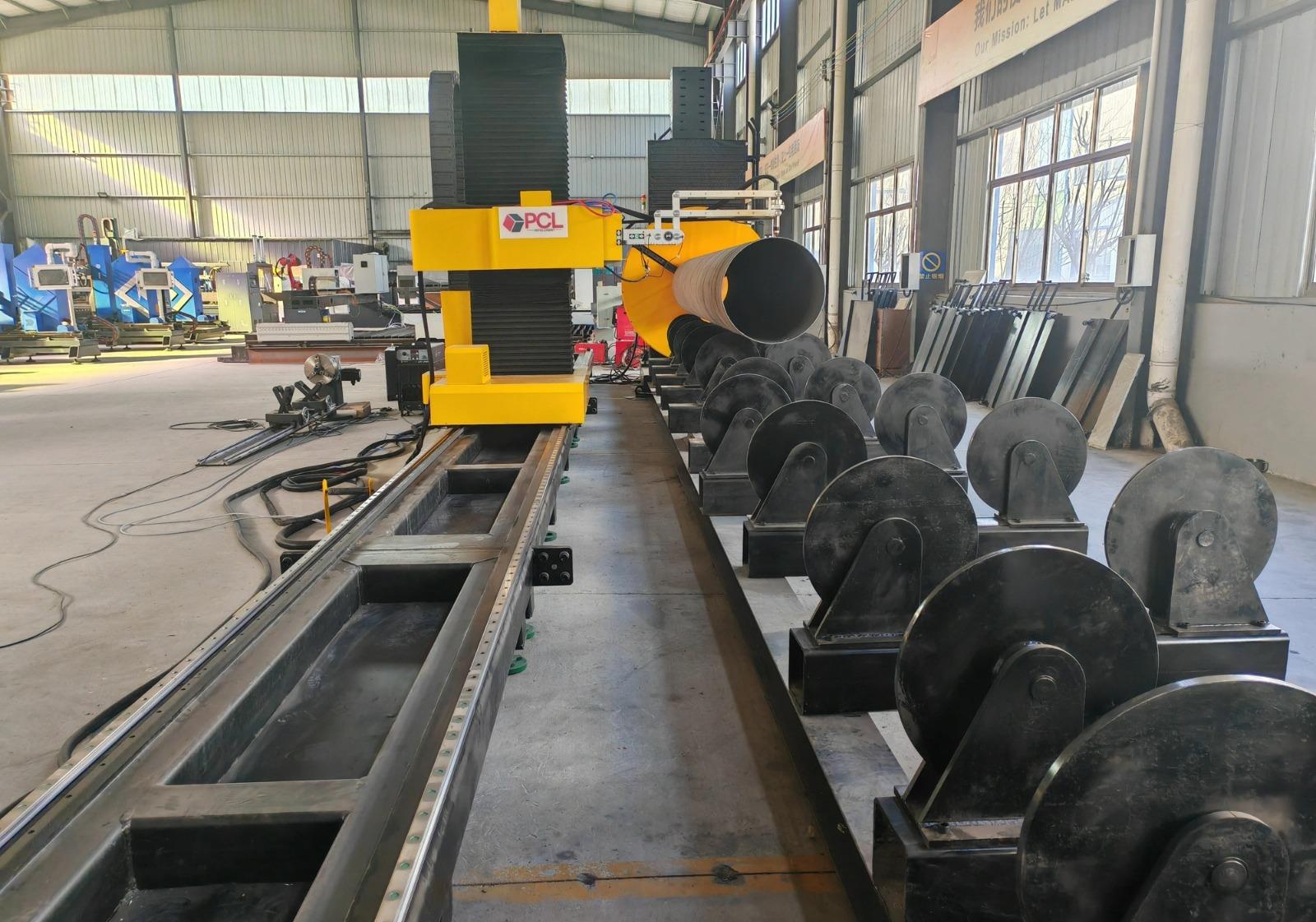
Achieving High-Precision Intersection Accuracy
Wind towers are complex cylindrical assemblies where internal structural beams must interface perfectly with the curved interior walls. Achieving intersection accuracy is critical to avoid large gaps that require excessive filler metal during subsequent assembly stages. Plasma cutting systems utilizing 4-axis or 5-axis kinematic heads can execute complex saddle cuts and miters with tight tolerances.
Mathematical Path Compensation
Modern plasma CNC controllers use real-time kerf compensation algorithms to account for the width of the plasma arc. Because the plasma jet is not a rigid tool, the software must calculate the lead-in and lead-out paths to ensure the inner dimensions of the intersection remain within a +/- 0.5mm tolerance. This level of precision is vital when cutting openings for cable conduits or ventilation ports in the tower shells, where the fit-up must be airtight and structurally sound.
Thermal Influence and Geometric Stability
Industrial engineers prioritize plasma for these intersections due to the balance between cutting speed and the Heat Affected Zone (HAZ). While high-definition plasma does introduce thermal energy, the speed at which it traverses the material limits the heat soak, preventing the warping of thin-gauge internal components. This ensures that the geometric profile of an H-beam flange or a channel section remains true to the CAD model, facilitating rapid bolt-hole alignment in the field.
H-Beam Processing and Low Maintenance Requirements
In the rugged environment of a wind tower fabrication facility, equipment durability is a primary driver of long-term ROI. Plasma systems are inherently robust, particularly when processing large-scale H-beams and structural steel. Unlike more delicate cutting technologies, the H-beam low maintenance profile of plasma systems is a result of the simplified torch consumable ecosystem and the absence of sensitive optical components.
Resilience in High-Dust Environments
The fabrication of wind towers generates significant metallic dust and debris. Plasma systems are designed with pressurized torch heads and high-flow filtration that protect the internal electrodes and nozzles. Maintenance cycles for plasma power sources are predictable, typically involving the scheduled replacement of nozzles, electrodes, and swirl rings. This predictability allows industrial engineers to schedule downtime during shift changes, ensuring the production line never stalls due to unplanned technical failures.
Consumable Lifecycle Management
Technological advancements in “LongLife” oxygen plasma have extended the pierce count and cut-meters per set of consumables. By monitoring the arc voltage, the system can automatically adjust the torch height to compensate for electrode wear. This ensures consistent cut quality throughout the shift, reducing the need for manual inspection of the bevel angle or surface roughness on the processed beams.
Advanced Beveling for Structural Integrity
The most critical phase of wind tower fabrication involves preparing the edges of heavy plates and structural sections for high-strength connections. Plasma beveling is the industry standard for creating V, Y, X, and K-shaped profiles. These profiles are essential for ensuring that the subsequent joinery meets the rigorous fatigue-strength requirements of offshore and onshore wind environments.
5-Axis Bevel Head Capabilities
The integration of a 5-axis plasma head allows for “on-the-fly” beveling, where the angle of the cut changes dynamically along a contoured path. In wind tower internals, this is particularly useful for platform supports that must be welded to the tapering inner diameter of the tower. The plasma system can cut the circular profile and the bevel simultaneously, eliminating the need for a secondary grinding operation.
Surface Quality and Edge Preparation
High-definition plasma systems produce a surface finish that is often weld-ready. By optimizing the gas mix (typically using oxygen for carbon steel), the plasma arc creates an edge with minimal dross and low carbon precipitation. This chemical cleanliness is vital for the integrity of the tower, as any impurities on the beveled edge could lead to porosity or inclusions in the final structure. The ability to maintain a consistent bevel angle across thick sections (up to 50mm or more) ensures that the volume of the weld groove remains constant, leading to more predictable manufacturing costs and timelines.
Conclusion for Industrial Planning
For the industrial engineer, the selection of a zero-tailing plasma cutting system is a strategic decision that impacts the entire wind tower production value chain. By focusing on the mechanical advantages of zero-tailing—specifically the elimination of material waste and the reduction of manual scrap handling—facilities can achieve a leaner workflow. Furthermore, the combination of high intersection accuracy and the low maintenance requirements of the plasma hardware ensures that the facility can meet aggressive delivery schedules without compromising on the geometric tolerances required for these massive structures. As the demand for renewable energy infrastructure grows, the efficiency of the plasma cutting process remains a cornerstone of competitive tower manufacturing.
-


Cantilever Welding Robot solution
-


GF laser cutting machine
-

P3015 plasma cutting machine
-

LFP3015 Fiber Laser Cutter
-

pipe plasma cutting machine
-
LFH 4020 Fiber Laser Cutting Machine
-
LFP4020
-

gantry plasma air cutting machine
-

3D robot cutting machine
-

8 axis plasma cutting machine
-

5 axis plasma cutting machine
-

LT360 tube laser cutting machine
-

robot welding workstation
-

SF6060 fiber laser cutting machine
Advanced Fiber Laser Tube Processing Technology
Our CNC Fiber Laser Tube Cutting systems revolutionize metal fabrication by integrating high-precision cutting, punching, and profiling into a single automated workflow. Designed for versatility, this technology handles a wide array of profiles including Round, Square, Rectangular, and Oval tubes, as well as complex L-shaped and U-shaped channels.
- Precision Punching: High-speed hole punching with micron-level accuracy, eliminating the need for mechanical drilling or die-stamping.
- Complex Profiling: Advanced 3D pathing allows for intricate interlocking joints and specialized notch cuts, ideal for structural frames.
- High Material Efficiency: Intelligent nesting software minimizes scrap, reducing raw material costs across large production runs.
- Clean Finish: Delivers oxide-free, burr-free edges that require zero secondary grinding before welding.

Seamlessly processing multiple profiles with consistent precision.
Global Delivery & Logistics



From our high-tech manufacturing facility directly to your global site. PCL WeldCut ensures secure packaging, professional handling, and reliable international logistics to safeguard your equipment throughout the entire journey.