Optimizing Material Yield with Zero-tailing technology
In the structural steel industry, material cost accounts for a significant portion of the total project budget. Traditional thermal cutting processes for H-beams, channels, and angles typically result in a “tail” or “dead zone”—a section of the profile that the machine’s clamping system cannot reach, usually ranging from 300mm to 800mm. This results in direct material waste and increased handling costs. The integration of Zero-tailing technology into a Plasma Cutting Machine resolves this inefficiency by utilizing a multi-chuck or pass-through feeding mechanism. This system allows the cutting head to access the absolute end of the workpiece, ensuring that the final part is cut precisely where the material terminates.
From an industrial engineering perspective, the elimination of this scrap improves the “buy-to-fly” ratio of the steel profiles. For a facility processing 500 tons of structural steel per month, reducing the scrap rate by even 3% through zero-tailing translates into substantial annual savings. This technology relies on sophisticated sensors and synchronized motion control between the longitudinal feeder and the cutting gantry, ensuring that the profile remains stable even when the center of gravity shifts during the final cut.
Intersection Accuracy and Structural Integrity
The complexity of modern Steel structure design requires intricate intersections where beams meet at various angles or where pipe-to-beam joints occur. High-definition plasma systems offer the necessary arc stability to maintain tight tolerances during these complex maneuvers. Unlike older air-plasma systems, high-definition units use oxygen or nitrogen as plasma gases to create a constricted, high-energy arc that minimizes kerf width and maximizes perpendicularity.
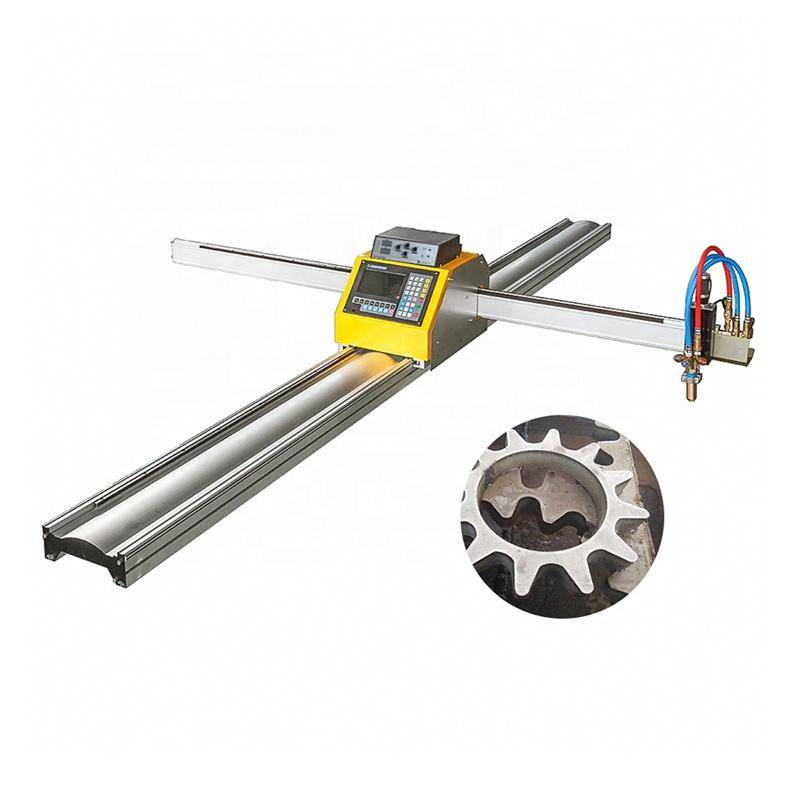
The intersection accuracy is critical for bolt-hole alignment and slot-and-tab assemblies. If the intersection profile deviates by more than 1mm, the subsequent assembly requires manual grinding or forced fit-up, both of which introduce secondary stresses into the structure. A multi-axis plasma system utilizes advanced nesting software to calculate the exact tool path for these intersections, compensating for the torch angle and the material thickness in real-time. This results in a “plug-and-play” component that fits perfectly into the master assembly on the construction site.
Low Maintenance Requirements in H-Beam Processing
One of the primary advantages of plasma technology in a heavy industrial environment is its inherent robustness. Steel fabrication shops are characterized by metallic dust, vibration, and temperature fluctuations—conditions that can be detrimental to sensitive equipment. A Plasma cutting machine is designed to operate reliably under these conditions. The torch components (shield, nozzle, electrode) are consumable items that are easily replaced by the operator without requiring specialized technical intervention or clean-room environments.
For H-beam processing specifically, the maintenance profile is significantly lower than alternative thermal processes. The absence of complex optical paths means that vibration from heavy overhead cranes or the loading of 12-meter beams does not misalign the cutting source. Furthermore, modern plasma power sources feature self-diagnostic capabilities that monitor coolant flow, gas pressure, and arc voltage. This predictive maintenance approach allows facilities to schedule downtime during non-production shifts, ensuring the machine maintains a high OEE (Overall Equipment Effectiveness) rating.
Advanced Beveling for Enhanced Weld Preparation
Structural steel requires specific edge geometries to ensure deep penetration during the welding process. Weld preparation typically involves creating V, Y, X, or K-cut bevels. A 5-axis plasma head can rotate and tilt during the cutting process to produce these bevels automatically. This eliminates the need for secondary operations, such as manual grinding or the use of portable beveling machines, which are labor-intensive and prone to human error.
The plasma beveling process is optimized by torch height control (THC) systems that respond to the surface irregularities of the H-beam flanges. Since hot-rolled steel often has slight deviations in flatness, the THC maintains a constant standoff distance between the nozzle and the plate. This consistency is vital for maintaining a constant bevel angle across the entire length of the cut. By achieving a precise bevel directly from the cutting table, the facility reduces the total man-hours per ton of fabricated steel.
Kinematics and Motion Control in Profile Cutting
The mechanical efficiency of a zero-tailing system depends on the kinematics of the gantry and the chuck system. In a typical setup, the primary chuck moves the profile along the X-axis while the plasma torch moves on the Y and Z axes, complemented by the A and B axes for beveling. When the end of the beam is reached, a secondary clamping unit or a specialized “sliding” chuck takes over to support the material, allowing the torch to pass through the space previously occupied by the primary clamp.
This seamless transition requires a high-speed PLC (Programmable Logic Controller) capable of processing encoder feedback from multiple motors simultaneously. The software must account for the physical dimensions of the chuck to prevent collisions while maximizing the reach of the torch. This level of automation reduces the reliance on skilled labor, as the machine autonomously handles the geometry calculations and material positioning once the CNC program is loaded.
Environmental and Operational Considerations
Modern plasma systems have made significant strides in reducing the environmental impact of structural steel fabrication. Integrated dust extraction systems and water tables effectively capture the fine particulate matter and fumes generated during the thermal process. Furthermore, the speed of plasma cutting on thick structural sections (20mm to 50mm) is significantly higher than oxy-fuel cutting, leading to lower energy consumption per meter of cut.
From an operational standpoint, the versatility of plasma allows it to cut various grades of steel, including high-strength alloys and galvanized coatings, without requiring significant adjustments to the machine setup. This flexibility is essential for job shops that handle a diverse range of structural projects, from industrial warehouses to complex architectural bridges. The combination of high speed, low maintenance, and zero-waste material handling makes the Plasma cutting machine the centerpiece of an efficient structural fabrication workflow.
Conclusion: The Engineering Case for Zero-Tailing Plasma
Implementing Zero-tailing technology is not merely a feature upgrade; it is a strategic decision to optimize the entire production chain. By ensuring that every millimeter of a steel profile is utilized, and every cut is prepared for immediate assembly with high-precision beveling, manufacturers can significantly reduce their overhead. The reliability of plasma in the harsh conditions of a steel mill or fabrication shop ensures that production targets are met without the frequent interruptions associated with more delicate technologies. For the industrial engineer, the focus remains on throughput, accuracy, and cost-reduction—three metrics where high-definition plasma cutting continues to excel.
-


Cantilever Welding Robot solution
-


GF laser cutting machine
-

P3015 plasma cutting machine
-

LFP3015 Fiber Laser Cutter
-

pipe plasma cutting machine
-
LFH 4020 Fiber Laser Cutting Machine
-
LFP4020
-

gantry plasma air cutting machine
-

3D robot cutting machine
-

8 axis plasma cutting machine
-

5 axis plasma cutting machine
-

LT360 tube laser cutting machine
-

robot welding workstation
-

SF6060 fiber laser cutting machine
Advanced Fiber Laser Tube Processing Technology
Our CNC Fiber Laser Tube Cutting systems revolutionize metal fabrication by integrating high-precision cutting, punching, and profiling into a single automated workflow. Designed for versatility, this technology handles a wide array of profiles including Round, Square, Rectangular, and Oval tubes, as well as complex L-shaped and U-shaped channels.
- Precision Punching: High-speed hole punching with micron-level accuracy, eliminating the need for mechanical drilling or die-stamping.
- Complex Profiling: Advanced 3D pathing allows for intricate interlocking joints and specialized notch cuts, ideal for structural frames.
- High Material Efficiency: Intelligent nesting software minimizes scrap, reducing raw material costs across large production runs.
- Clean Finish: Delivers oxide-free, burr-free edges that require zero secondary grinding before welding.

Seamlessly processing multiple profiles with consistent precision.
Global Delivery & Logistics



From our high-tech manufacturing facility directly to your global site. PCL WeldCut ensures secure packaging, professional handling, and reliable international logistics to safeguard your equipment throughout the entire journey.