Optimizing Maritime Fabrication with Zero-Tailing Plasma Systems
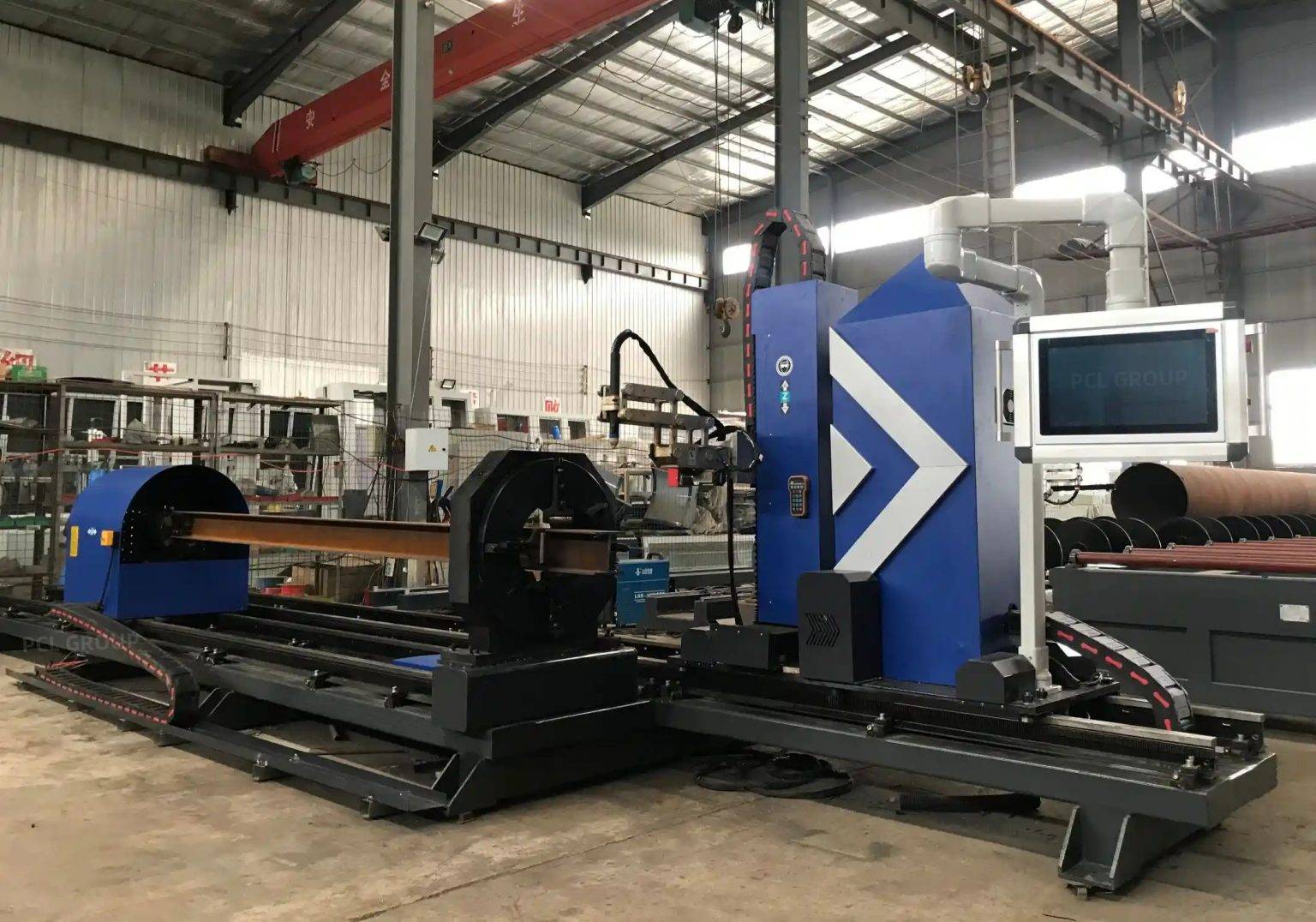
In the competitive landscape of global shipbuilding, structural efficiency and material conservation are the primary drivers of profitability. The integration of a Plasma Cutting Machine designed specifically for heavy profiles marks a transition from traditional mechanical processing to high-precision thermal fabrication. Unlike standard cutting systems that require significant clamping margins, zero-tailing technology allows the machine to process the entire length of an H-beam, bulb flat, or angle bar without leaving unusable remnants. This capability is critical when dealing with high-grade marine steels where scrap costs can significantly impact the total cost of ownership.
Engineering Fundamentals of Zero-Tailing Technology
Zero-tailing is achieved through a coordinated dual-chuck or multi-gripper feed system. In a standard industrial setup, the “tail” of a profile is often lost because the material cannot be safely held while the torch reaches the final edge. In a zero-tailing technology configuration, the machine utilizes a primary feed chuck and a secondary output chuck. As the cut nears the end of the profile, the secondary chuck takes control of the workpiece, allowing the plasma torch to maintain its focal point and gas pressure right to the absolute edge of the material.
From an industrial engineering perspective, this eliminates the 300mm to 500mm of scrap typically associated with each structural member. For a shipyard processing thousands of tons of steel annually, the cumulative material recovery translates into a direct increase in the material utilization rate by 3% to 5%. This mechanical synchronization requires sophisticated CNC algorithms that compensate for slight variations in material straightness and rotational inertia during the transition between chucks.
Achieving Superior Intersection Accuracy in Complex Geometries
The structural integrity of a vessel depends on the fit-up quality of its internal ribbing and bulkheads. Intersection accuracy refers to the precision with which the plasma torch executes complex cuts where one profile meets another at an angle, such as a pipe-to-H-beam joint or a mitered corner. Modern plasma systems utilize advanced 6-axis robotic arms or specialized gantry heads to maintain the torch’s perpendicularity and kerf compensation throughout the entire cutting path.
For shipbuilders, this precision reduces the need for secondary grinding and manual fit-up. If the intersection is accurate to within +/- 0.5mm, the assembly team can move directly to joining the components. High-definition plasma power sources play a vital role here, utilizing oxygen-based plasma gas for carbon steels to produce a narrower kerf and a smaller heat-affected zone (HAZ). This ensures that the metallurgical properties of the ship’s structural steel remain intact, preventing brittleness at the connection points.
H-Beam Processing and Low Maintenance Requirements
H-beams are the backbone of maritime structural engineering, often serving as main longitudinals or heavy equipment supports. Processing these beams in a high-volume shipyard environment requires equipment that can withstand dust, vibration, and continuous operation. One of the primary advantages of plasma systems in H-beam processing is their mechanical robustness.
A plasma cutting machine is inherently suited for the harsh environments of a shipyard. The torch components—nozzles, electrodes, and swirl rings—are consumable and easily replaceable by operators without specialized technical training. Unlike systems with complex optical paths or delicate mirrors, plasma systems utilize robust copper cables and gas hoses. This reduces downtime significantly. Maintenance schedules are predictable, focusing on gas filtration and rack-and-pinion lubrication, ensuring that the machine remains operational across three-shift cycles.
Advanced Automated Beveling for Weld Preparation
Effective welding in shipbuilding requires specific edge geometries, including V-grooves, Y-grooves, and K-profiles. Automated beveling using a multi-axis plasma head allows these profiles to be cut directly into the workpiece during the primary processing phase. This eliminates the need for a separate beveling station or manual oxy-fuel torches.
The CNC system adjusts the torch angle in real-time, compensating for the changes in material thickness encountered during the beveling of an H-beam’s flange-to-web transition. By integrating the beveling process, the shipyard reduces the number of material handling steps. Every time a heavy beam is moved by a crane, there is a risk of injury and a cost in time. Cutting, hole-drilling, and beveling in a single pass on a plasma machine optimizes the entire production flow.
Thermal Management and Kerf Compensation
A critical aspect of industrial engineering in plasma cutting is managing the thermal expansion of the steel. As the plasma arc introduces intense heat, the beam can expand or bow. Advanced machines counteract this through real-time sensing. Initial height sensing (IHS) and arc voltage height control (AVHC) ensure that the torch maintains a constant distance from the material, even if the beam is not perfectly flat.
Kerf compensation is another vital factor. The software calculates the width of the material removed by the plasma arc and adjusts the tool path outward. This ensures that the final dimensions of the part match the CAD model exactly. For maritime applications where large sections must be modularly joined, this dimensional consistency is non-negotiable.
Workflow Integration and Throughput Analysis
The implementation of a zero-tailing plasma system should be viewed through the lens of total throughput. Traditional methods involving manual marking, sawing, and drilling are bottlenecks. A CNC plasma system acts as a unified workstation. The workflow begins with the import of DSTV or XML files from ship design software. The nesting engine then optimizes the parts on the raw beams to maximize the benefits of zero-tailing technology.
Once the cutting cycle begins, the machine operates with minimal intervention. The high travel speeds of plasma—often exceeding 6,000mm/min on thinner webs—allow for rapid cycle times. When combined with the reduction in scrap and the elimination of secondary edge preparation, the return on investment (ROI) is typically realized within 12 to 18 months, depending on the shipyard’s volume.
Conclusion: The Future of Maritime Structural Fabrication
For the industrial engineer, the choice of a plasma-based profile cutting system is a balance of precision, durability, and cost-efficiency. By prioritizing zero-tailing capabilities and intersection accuracy, shipyards can significantly reduce material waste and labor costs. The ability to handle heavy H-beams with minimal maintenance ensures that the production line remains fluid, meeting the tight deadlines of modern vessel construction. Plasma technology continues to be the workhorse of the maritime industry, providing the necessary power and flexibility to shape the massive steel structures of tomorrow’s fleet.
-


LT240S tube laser cutting machine
-
LT120S tube laser cutting machine
-
Sale

Tank Fillet Welding Machine
Original price was: $1,000.00.$900.00Current price is: $900.00. -
Sale

MAK100 tube laser cutting machine
Original price was: $5,500.00.$5,000.00Current price is: $5,000.00. -

portable plasma air cutting machine
$1,200.00 -

2in1 fiber laser cutting machine
-

Air cooling Laser welding machine
-

HF h beam laser cutting machine
-

LT240 laser cutting machine
-

Laser welding machine
-


Cobot Welding Station
-

Gantry welding robot solution
-

Tracked Wheeled AGV Welding robot
-

LFH6020 Fiber laser cutting machine
-
LFP6020
-

robotic welidng machine
Advanced Fiber Laser Tube Processing Technology
Our CNC Fiber Laser Tube Cutting systems revolutionize metal fabrication by integrating high-precision cutting, punching, and profiling into a single automated workflow. Designed for versatility, this technology handles a wide array of profiles including Round, Square, Rectangular, and Oval tubes, as well as complex L-shaped and U-shaped channels.
- Precision Punching: High-speed hole punching with micron-level accuracy, eliminating the need for mechanical drilling or die-stamping.
- Complex Profiling: Advanced 3D pathing allows for intricate interlocking joints and specialized notch cuts, ideal for structural frames.
- High Material Efficiency: Intelligent nesting software minimizes scrap, reducing raw material costs across large production runs.
- Clean Finish: Delivers oxide-free, burr-free edges that require zero secondary grinding before welding.

Seamlessly processing multiple profiles with consistent precision.
Global Delivery & Logistics



From our high-tech manufacturing facility directly to your global site. PCL WeldCut ensures secure packaging, professional handling, and reliable international logistics to safeguard your equipment throughout the entire journey.