Optimization of Shipbuilding Through Zero-Tailing Plasma Technology
In the heavy industry of shipbuilding, material efficiency and structural integrity are the primary drivers of profitability. Traditional thermal cutting processes for long structural profiles—such as H-beams, I-beams, and bulb flats—often suffer from a significant drawback: “tailing” waste. This refers to the unusable 400mm to 800mm of material at the end of a beam that the machine’s feeding system cannot reach. The introduction of zero-tailing technology has redefined the ROI for shipyards by utilizing specialized dual-chuck or multi-gripper feeding mechanisms that allow the plasma torch to process the entire length of the raw material. From an industrial engineering perspective, this eliminates the scrap-end cost and maximizes the number of parts extracted from a single stock length.
Mechanical Architecture of Zero-Tailing Systems
The core of a zero-tailing plasma machine lies in its material handling synchronization. Conventional machines rely on a single pushing carriage that releases the beam before it reaches the cutting zone to avoid collision with the torch. A zero-tailing system utilizes a secondary clamping unit or a “pass-through” gripper that maintains control of the workpiece as it moves through the cutting envelope. This allows the plasma arc to strike at the very edge of the beam’s trailing end. For a shipyard processing thousands of tons of steel annually, the reduction of a 500mm waste piece per beam translates into hundreds of thousands of dollars in annual material savings.
Intersection Accuracy in Complex Maritime Structures
Ship hulls and internal frames require complex intersections where various profiles meet at non-perpendicular angles. Intersection accuracy is critical because gaps larger than 1.5mm often require manual filler work or lead to structural weaknesses under high-stress maritime conditions. High-definition plasma systems, controlled by sophisticated 6-axis robotic arms or specialized CNC gantry heads, calculate the kerf compensation and the exact 3D path required for these joints. Whether it is a pipe-to-H-beam intersection or a bulb flat passing through a transverse bulkhead, the plasma arc maintains a consistent standoff distance. This precision ensures that the “fit-up” phase of assembly is seamless, reducing the need for costly corrective grinding on the shop floor.
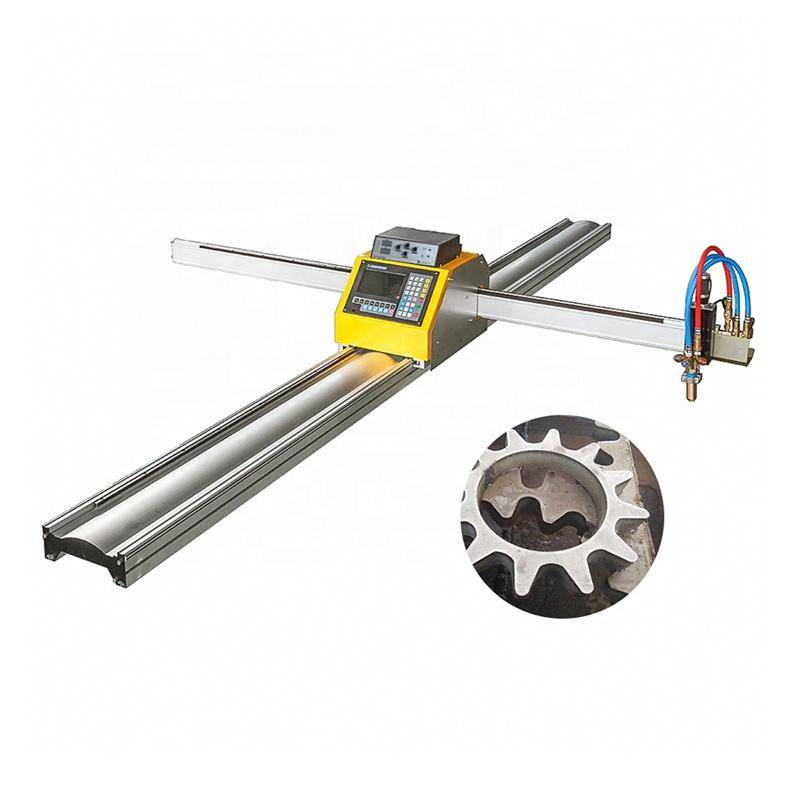
The Maintenance Profile of Plasma Systems in H-Beam Processing
When evaluating the lifecycle cost of cutting equipment, maintenance downtime is a critical metric. H-beam low maintenance is a primary advantage of plasma technology in the dusty, vibration-heavy environment of a shipyard. Unlike high-sensitivity optical systems, plasma systems are robust. The primary maintenance tasks are limited to the replacement of consumables—nozzles, electrodes, and swirl rings—which can be performed by the operator in under two minutes.
Robustness in Harsh Environments
Shipyard environments are characterized by airborne particulates, fluctuating temperatures, and heavy vibrations from overhead cranes. Plasma power sources are designed with high duty cycles (often 100% at maximum output) and are isolated from the most sensitive electronic components via pressurized cooling systems. The “low maintenance” aspect also extends to the beam delivery. Since the plasma arc is an electrical discharge through a gas medium, there are no complex lenses or mirrors to align. This ensures that the machine remains operational across three-shift schedules with minimal intervention from specialized service engineers.
Advanced Beveling for Weld Preparation
Welding in shipbuilding requires deep penetration to withstand the hydrodynamic forces and cargo loads encountered at sea. Therefore, almost every structural edge must be beveled. Modern Plasma Cutting Machines feature a rotating 3D head capable of performing V, Y, K, and X-type bevels in a single pass. Beveling accuracy is maintained through torch height control (THC) and real-time voltage sensing, which compensates for any slight warping in the steel plate or beam web.
By integrating the beveling process directly into the cutting cycle, industrial engineers can eliminate the “second station” bottleneck. In traditional workflows, a part is cut to shape and then moved to a separate station for manual beveling with a hand-held grinder or a dedicated beveller. A 5-axis plasma head performs this during the initial cut, ensuring that the bevel angle is perfectly consistent along the entire contour of the part. This consistency is vital for automated welding systems that require a uniform groove for high-quality bead deposition.
Kinematic Precision and Kerf Management
The industrial engineer must also account for the kerf—the width of the material removed by the plasma arc. In high-definition plasma, the arc is constricted by a specialized nozzle and a secondary shielding gas, resulting in a narrower kerf and a squarer cut edge compared to standard air-plasma systems. When processing H-beams for ship ribs, the machine’s software must dynamically adjust the feed rate and gas pressure as the torch transitions from the thin web to the thicker flanges. This dynamic adjustment is what ensures the intersection accuracy mentioned previously. The CNC controller uses look-ahead logic to slow down the torch at corners, preventing “rounding” of the cut and ensuring that the structural integrity of the joint is not compromised by over-travel.
Integration with Shipbuilding CAD/CAM
The effectiveness of a zero-tailing plasma machine is maximized when it is tightly integrated with shipbuilding-specific software like AVEVA, Tribon, or ShipConstructor. These programs generate the NC code that includes “nesting” logic optimized for zero-tailing. The software identifies which parts can be placed at the very end of a beam to utilize the material that would otherwise be discarded. Furthermore, the software communicates the precise bevel angles and intersection paths directly to the 6-axis controller, eliminating human error in the data translation process.
Conclusion on Operational Efficiency
The transition to a zero-tailing plasma cutting workflow represents a strategic shift for modern shipyards. By focusing on the mechanical reliability of plasma—noted for its H-beam low maintenance and resilience—facilities can maintain high throughput without the fragility of more sensitive technologies. The ability to achieve high intersection accuracy and complex beveling in a single setup directly reduces the labor hours per ton of steel processed. Ultimately, the elimination of the “tailing” waste through advanced clamping and feeding mechanisms provides a measurable boost to material yield, ensuring that every centimeter of structural steel is utilized in the construction of the vessel.
-


LT240S tube laser cutting machine
-
LT120S tube laser cutting machine
-
Sale

Tank Fillet Welding Machine
Original price was: $1,000.00.$900.00Current price is: $900.00. -
Sale

MAK100 tube laser cutting machine
Original price was: $5,500.00.$5,000.00Current price is: $5,000.00. -

portable plasma air cutting machine
$1,200.00 -

2in1 fiber laser cutting machine
-

Air cooling Laser welding machine
-

HF h beam laser cutting machine
-

LT240 laser cutting machine
-

Laser welding machine
-


Cobot Welding Station
-

Gantry welding robot solution
-

Tracked Wheeled AGV Welding robot
-

LFH6020 Fiber laser cutting machine
-
LFP6020
-

robotic welidng machine
Advanced Fiber Laser Tube Processing Technology
Our CNC Fiber Laser Tube Cutting systems revolutionize metal fabrication by integrating high-precision cutting, punching, and profiling into a single automated workflow. Designed for versatility, this technology handles a wide array of profiles including Round, Square, Rectangular, and Oval tubes, as well as complex L-shaped and U-shaped channels.
- Precision Punching: High-speed hole punching with micron-level accuracy, eliminating the need for mechanical drilling or die-stamping.
- Complex Profiling: Advanced 3D pathing allows for intricate interlocking joints and specialized notch cuts, ideal for structural frames.
- High Material Efficiency: Intelligent nesting software minimizes scrap, reducing raw material costs across large production runs.
- Clean Finish: Delivers oxide-free, burr-free edges that require zero secondary grinding before welding.

Seamlessly processing multiple profiles with consistent precision.
Global Delivery & Logistics



From our high-tech manufacturing facility directly to your global site. PCL WeldCut ensures secure packaging, professional handling, and reliable international logistics to safeguard your equipment throughout the entire journey.