Optimizing Pressure Vessel Fabrication with Zero-Tailing Plasma Technology
In the heavy industrial landscape of pressure vessel manufacturing, the margin for error is non-existent. Engineers are tasked with balancing structural integrity, compliance with ASME Section VIII standards, and material efficiency. The emergence of zero-tailing technology in Plasma Cutting systems has redefined the workflow for processing large-diameter pipes and vessel shells. This technology addresses one of the most persistent drains on profitability: the wasted material at the end of a production run, often referred to as the “tail” or “remnant.”
The Mechanics of Zero-Tailing in Heavy-Duty Cutting
Traditional plasma pipe cutting machines require a minimum clamping distance between the chuck and the cutting torch to prevent mechanical interference. This typically results in 400mm to 800mm of unusable pipe per length. In pressure vessel fabrication, where specialized alloys and thick-walled carbon steels are standard, this waste represents a significant capital loss.
Zero-tailing systems utilize a multi-chuck or a pass-through modular clamping mechanism that allows the cutting torch to reach the absolute edge of the material. By synchronizing the movement of the rotational axis with the longitudinal travel of the gantry, the system can process the entire length of the stock. For an industrial facility processing 500 tons of pipe annually, eliminating a 5% waste margin translates directly into measurable ROI and a leaner supply chain.
Precision Intersection Accuracy for Nozzle Fitment
The core challenge in vessel assembly is the intersection of the nozzle and the main shell. Whether it is a centered saddle cut or an offset lateral, the geometry is complex. Plasma cutting intersection accuracy is the determining factor in whether a vessel requires hours of manual grinding or moves directly to the assembly floor.
Advanced Kinematics and Motion Control
Achieving high-precision intersections requires a 4-axis or 6-axis motion control system. The plasma torch must not only follow the elliptical path of the intersection but also dynamically adjust its tilt to maintain the correct root gap and bevel angle throughout the circumference. Modern plasma systems utilize real-time kerf compensation and surface mapping to ensure that the actual cut matches the CAD model within a tolerance of +/- 0.5mm.
This level of accuracy is critical for high-pressure environments. A precise fit ensures uniform heat distribution during subsequent welding processes, minimizing the risk of lamellar tearing or hydrogen-induced cracking in the heat-affected zone (HAZ). When the intersection is cut with high fidelity, the volumetric integrity of the vessel is preserved, and the likelihood of failing a radiographic or ultrasonic test is drastically reduced.
Beveling Capabilities for Deep Penetration Requirements
Pressure vessels often exceed 25mm in wall thickness, necessitating complex bevel profiles for full-penetration welds. Plasma cutting remains the industry standard for these applications due to its ability to maintain high speeds on thick sections without the thermal distortion seen in oxy-fuel or the thickness limitations of other methods.
Multi-Axis Beveling Profiles
The integration of a robotic or 5-axis plasma head allows for the execution of V, Y, X, and K-style bevels in a single pass. Pressure vessel fabrication relies on these profiles to ensure that the weld metal can reach the root of the joint. The ability to program varying bevel angles along a single cut path is particularly useful for saddle intersections where the angle of the joint changes continuously as the torch moves around the pipe. This “variable beveling” capability eliminates the need for secondary edge preparation, significantly reducing the total man-hours per vessel.
Managing the Heat-Affected Zone (HAZ)
From an industrial engineering perspective, the metallurgical impact of the cut is as important as the geometry. High-definition plasma systems use oxygen or nitrogen-shielded gases to produce a clean, dross-free edge. This limits the depth of the HAZ, ensuring that the base metal properties remain within the specified ranges for tensile strength and ductility. For vessels operating in cryogenic or high-temperature service, maintaining these material properties is a safety imperative.
H-Beam Structural Design and Low Maintenance Operations
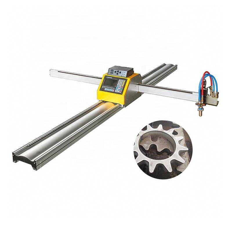
The reliability of a plasma cutting system is heavily dependent on its structural foundation. High-performance machines utilize an H-beam gantry and rail design. This choice of geometry is intentional; H-beams provide superior torsional rigidity and vibration damping compared to lighter tubular frames.
The Engineering Advantage of H-Beam Rails
In a heavy fabrication environment, the floor is subject to vibrations from overhead cranes, forklifts, and plate rollers. A cutting system mounted on a precision-ground H-beam rail system maintains its alignment over years of service. This stability is critical for maintaining plasma cutting intersection accuracy over long spans.
Furthermore, H-beam designs allow for an open-bed architecture that simplifies slag management. In high-volume plasma cutting, the accumulation of dross and metallic dust can interfere with the drive systems. By utilizing heavy-duty H-beams with shielded linear guides, maintenance intervals are extended. The removal of waste material is streamlined, and the critical rack-and-pinion drive components remain protected from the abrasive environment. This translates to a lower Total Cost of Ownership (TCO) and higher machine uptime.
Sensor Integration and Consumable Longevity
Modern plasma systems incorporate arc voltage height control (AVHC) and collision detection sensors. These systems work in tandem with the rigid H-beam frame to prevent torch damage and ensure consistent cut quality. By maintaining the optimal standoff distance, the system maximizes the life of electrodes and nozzles, further reducing operational costs.
Conclusion: Integrating Efficiency into the Fabrication Cycle
For the industrial engineer, the selection of a plasma cutting system for Pressure Vessels is a decision based on throughput, precision, and material utilization. Zero-tailing technology removes the bottleneck of material waste, while advanced multi-axis motion control ensures that complex intersections and bevels meet the most stringent quality codes. By opting for a machine built on a robust H-beam platform, manufacturers secure a long-term asset that requires minimal maintenance while delivering the high-accuracy cuts necessary for the demanding world of pressure vessel manufacturing. The synergy of these technologies allows for a streamlined production flow where “right-first-time” is the standard, not the exception.
-


Cantilever Welding Robot solution
-


GF laser cutting machine
-

P3015 plasma cutting machine
-

LFP3015 Fiber Laser Cutter
-

pipe plasma cutting machine
-
LFH 4020 Fiber Laser Cutting Machine
-
LFP4020
-

gantry plasma air cutting machine
-

3D robot cutting machine
-

8 axis plasma cutting machine
-

5 axis plasma cutting machine
-

LT360 tube laser cutting machine
-

robot welding workstation
-

SF6060 fiber laser cutting machine
Advanced Fiber Laser Tube Processing Technology
Our CNC Fiber Laser Tube Cutting systems revolutionize metal fabrication by integrating high-precision cutting, punching, and profiling into a single automated workflow. Designed for versatility, this technology handles a wide array of profiles including Round, Square, Rectangular, and Oval tubes, as well as complex L-shaped and U-shaped channels.
- Precision Punching: High-speed hole punching with micron-level accuracy, eliminating the need for mechanical drilling or die-stamping.
- Complex Profiling: Advanced 3D pathing allows for intricate interlocking joints and specialized notch cuts, ideal for structural frames.
- High Material Efficiency: Intelligent nesting software minimizes scrap, reducing raw material costs across large production runs.
- Clean Finish: Delivers oxide-free, burr-free edges that require zero secondary grinding before welding.

Seamlessly processing multiple profiles with consistent precision.
Global Delivery & Logistics



From our high-tech manufacturing facility directly to your global site. PCL WeldCut ensures secure packaging, professional handling, and reliable international logistics to safeguard your equipment throughout the entire journey.