Optimizing Pressure Vessel Fabrication with Zero-Tailing Plasma Technology
In the heavy manufacturing landscape, the efficiency of pressure vessel production is dictated by the precision of raw material processing. Industrial engineers are increasingly turning to Zero-tailing Plasma Cutting systems to address the dual challenges of high material costs and rigorous structural requirements. Unlike standard pipe cutting methods that result in significant scrap at the end of each workpiece, zero-tailing technology utilizes advanced chucking configurations to ensure that the plasma torch can operate across the entire length of the pipe or shell. This approach directly impacts the bottom line by increasing the nesting density and reducing the “dead zone” typically found in traditional rotary drives.
Mechanical Architecture and Material Utilization
The core of zero-tailing technology lies in its clamping mechanism. In a standard pressure vessel fabrication setup, the pipe is held by a single chuck or set of rollers, leaving a substantial tailing piece that cannot be safely processed due to stability issues. A zero-tailing system employs a secondary movable chuck or a specialized feeding system that passes the material through the cutting zone with continuous support. This ensures that even the final segments of high-value alloy piping are utilized for small-bore nozzles or reinforcement rings.
From an industrial engineering perspective, the reduction of scrap from 400mm to less than 50mm per length of pipe represents a significant increase in material yield. When dealing with expensive specialized steels required for high-pressure environments, the ROI on a zero-tailing plasma system is often realized within the first year of high-volume production. The ability to nest multiple components on a single raw length without worrying about the “end-of-pipe” limitation is a critical advantage in lean manufacturing.
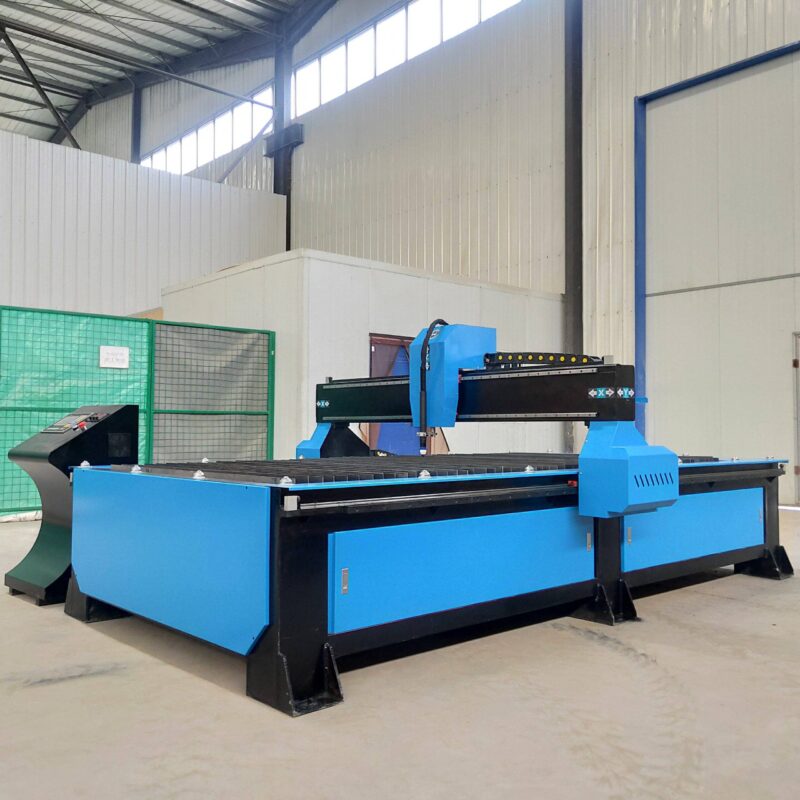
Precision Intersection Cutting for Nozzle Fit-Up
Pressure vessels are defined by their complex intersections. The junction where a nozzle meets the main shell or head requires a mathematically perfect saddle cut to ensure structural integrity and facilitate a high-quality weld. Plasma Cutting Machines equipped with 6-axis or 8-axis robotic heads provide the necessary degrees of freedom to execute these cuts with high intersection accuracy.
Mathematical Profiling and 3D Kinematics
The accuracy of an intersection cut is a function of the machine’s ability to synchronize the rotation of the vessel with the lateral and vertical movement of the plasma torch. Modern plasma systems utilize specialized software that calculates the intersection curve based on the diameters, wall thicknesses, and offset angles of the two mating components. This eliminates the need for manual layout and template making, which are prone to human error.
The plasma arc itself is stabilized by high-precision voltage controllers that maintain a constant distance between the torch and the uneven surface of the vessel. This is particularly important when cutting openings in dished heads or elliptical ends. The result is a kerf that is consistent in width and angle, ensuring that when the nozzle is placed into the shell, the gap is uniform and ready for immediate fit-up. This level of precision is vital for complying with ASME Section VIII or similar international pressure vessel standards.
Maintenance Advantages of Plasma Systems and H-Beam Frames
In a heavy industrial environment, the durability of the machinery is as important as its precision. Plasma cutting systems designed for Pressure Vessels often utilize heavy-duty H-beam structural frames. These frames provide the necessary rigidity to support large-diameter shells while maintaining H-beam low maintenance profiles compared to more delicate mechanical alternatives.
Structural Rigidity and Vibration Damping
The use of H-beams in the machine’s gantry and bed construction allows for superior vibration damping during high-speed plasma operations. Because plasma cutting is a non-contact process, the machine does not experience the reactive forces associated with mechanical milling or sawing. This reduces the wear and tear on bearings, drive motors, and rails. The H-beam structure ensures that the machine remains square and calibrated even under the thermal stresses common in a welding and cutting shop.
Simplified Consumable Management
Maintenance on a plasma system is largely confined to the torch consumables—nozzles, electrodes, and swirl rings. Modern systems feature “quick-change” torch designs that allow operators to resume production in minutes. Unlike mechanical tools that require sharpening or complex alignment, plasma consumables are standardized and easily replaced, ensuring that the machine’s uptime remains consistently high. Furthermore, the absence of complex liquid cooling systems for the optics (as seen in other technologies) simplifies the preventative maintenance schedule.
Advanced Beveling for Full Penetration Welds
For pressure vessels, the quality of the weld is non-negotiable. To achieve full penetration, the edges of the cut must be beveled at precise angles—often ranging from 20 to 45 degrees. Plasma cutting machines excel in this area through the use of plasma beveling heads that can rotate and tilt during the cutting process.
Variable Angle Beveling and Groove Preparation
In a single pass, a high-definition plasma torch can cut the hole for a nozzle and apply the required V, Y, or K-groove bevel. This integrated approach removes the need for secondary grinding or edge preparation, which is a major bottleneck in vessel fabrication. The consistency of the plasma arc ensures that the bevel angle remains constant throughout the entire circumference of the cut, regardless of the vessel’s curvature.
Industrial engineers focus on the Heat Affected Zone (HAZ) during plasma beveling. By optimizing the cutting speed and gas mixture (such as using Argon-Hydrogen or Oxygen-Nitrogen blends), the HAZ can be minimized, ensuring that the metallurgical properties of the pressure vessel steel are not compromised. This is essential for vessels that will undergo post-weld heat treatment (PWHT) or operate in corrosive environments where weld zone integrity is paramount.
Integration with Automated Workflows
The data-driven nature of modern plasma systems allows for seamless integration with PLM and ERP systems. The cutting parameters for every hole and bevel are logged, providing a digital twin of the fabrication process. This traceability is a requirement in many high-stakes industries, such as nuclear power or chemical processing, where every cut on a pressure vessel must be documented and verified against the original engineering specifications.
Conclusion on Process Optimization
The implementation of Zero-tailing plasma cutting technology represents a strategic shift in pressure vessel manufacturing. By prioritizing intersection accuracy and leveraging the robust, low-maintenance nature of plasma hardware, facilities can significantly reduce their cost per ton of fabricated steel. The ability to perform complex beveling and precision profiling in a single setup not only saves time but also ensures that the final assembly meets the highest safety and quality standards required for pressurized equipment.
-


Cantilever Welding Robot solution
-


GF laser cutting machine
-

P3015 plasma cutting machine
-

LFP3015 Fiber Laser Cutter
-

pipe plasma cutting machine
-
LFH 4020 Fiber Laser Cutting Machine
-
LFP4020
-

gantry plasma air cutting machine
-

3D robot cutting machine
-

8 axis plasma cutting machine
-

5 axis plasma cutting machine
-

LT360 tube laser cutting machine
-

robot welding workstation
-

SF6060 fiber laser cutting machine
Advanced Fiber Laser Tube Processing Technology
Our CNC Fiber Laser Tube Cutting systems revolutionize metal fabrication by integrating high-precision cutting, punching, and profiling into a single automated workflow. Designed for versatility, this technology handles a wide array of profiles including Round, Square, Rectangular, and Oval tubes, as well as complex L-shaped and U-shaped channels.
- Precision Punching: High-speed hole punching with micron-level accuracy, eliminating the need for mechanical drilling or die-stamping.
- Complex Profiling: Advanced 3D pathing allows for intricate interlocking joints and specialized notch cuts, ideal for structural frames.
- High Material Efficiency: Intelligent nesting software minimizes scrap, reducing raw material costs across large production runs.
- Clean Finish: Delivers oxide-free, burr-free edges that require zero secondary grinding before welding.

Seamlessly processing multiple profiles with consistent precision.
Global Delivery & Logistics



From our high-tech manufacturing facility directly to your global site. PCL WeldCut ensures secure packaging, professional handling, and reliable international logistics to safeguard your equipment throughout the entire journey.