Optimizing Oil and Gas Tank Fabrication via Plasma Systems
In the heavy industrial landscape of Oil and Gas, the fabrication of storage tanks and pressure vessels demands high-output machinery capable of handling thick-gauge carbon steel and stainless alloys. The primary engineering challenge lies in maintaining structural integrity while minimizing the cost per ton of fabricated steel. High-definition Plasma Cutting has emerged as the standard for this sector, particularly when integrated with zero-tailing technology. This advancement addresses the traditional waste generated during the tail-end of structural beam and pipe processing, allowing for near-100% material utilization.
From an industrial engineering perspective, the transition to zero-tailing plasma systems is not merely a capital expenditure but a strategic move to reduce the “scrap-to-product” ratio. In a sector where material costs fluctuate significantly, the ability to process the final 150mm to 300mm of a structural profile—sections previously discarded due to chucking limitations—translates directly into improved project margins.
The Mechanics of Zero-Tailing Technology
Zero-tailing is achieved through a dual-chuck or multi-gripper feeding system that maintains a positive grip on the workpiece throughout the entire cutting cycle. In traditional plasma centers, the distance between the chuck and the torch head creates a “dead zone” where the material cannot be stabilized for precise cutting. By utilizing synchronized secondary clamping units, the machine can pass the material through the cutting zone until the very edge of the profile is reached.
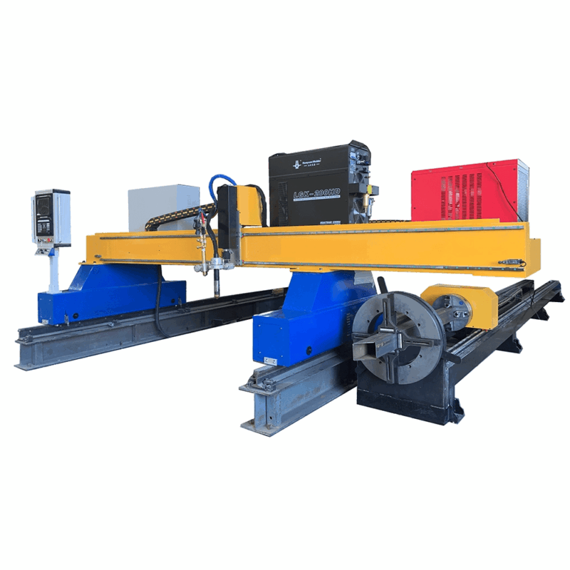
This capability is vital for Oil and Gas tanks, where structural reinforcements and secondary supports require various lengths of H-beams and I-beams. Eliminating the tailing allows for nesting algorithms to optimize the cut-path across the entire raw material length, reducing the frequency of remnant handling and secondary sorting operations.
Achieving Superior Intersection Accuracy
Oil and Gas tanks are complex assemblies of shells, floors, roofs, and internal support structures. The points where vertical columns meet horizontal cross-members or where curved shell plates interface with radial supports require intersection accuracy that leaves no room for manual adjustment during fit-up. Plasma Cutting Machines utilize advanced CNC controllers that compensate for kerf width and arc voltage fluctuations in real-time.
High-precision intersection cutting involves the synchronization of the rotary axis (for pipes or beams) with the 3D movement of the plasma torch. When cutting complex saddle joints or eccentric intersections for tank nozzle reinforcements, the plasma arc must maintain a consistent standoff distance to ensure edge perpendicularity. Modern plasma systems utilize capacitive height sensing and rapid-response motors to adjust for surface irregularities in the raw material, ensuring that every intersection point aligns perfectly with the CAD model.
Dimensional Tolerance and Structural Load
Precision at the intersection reduces the reliance on heavy-gap filling during the welding phase. For tank structural supports, a tight fit-up ensures that the load distribution across the H-beams and circular hollow sections (CHS) remains consistent with the design’s Finite Element Analysis (FEA). Any deviation in the cut angle or the curvature of the intersection can lead to localized stress concentrations, which are unacceptable in high-pressure or high-volume storage environments.
H-Beam Processing and Low Maintenance Requirements
The structural skeletons of large-scale oil tanks often rely on heavy H-beams. Utilizing plasma technology for H-beam processing offers a distinct advantage over mechanical drilling or sawing methods: reduced maintenance downtime. Mechanical systems involve high-wear components like drill bits, saw blades, and cooling lubricants that require constant replenishment and calibration.
Plasma cutting is a non-contact process. The primary wear components are limited to consumables such as nozzles, electrodes, and swirl rings. Because the torch does not apply physical force to the beam, there is no vibration-induced wear on the machine’s gantry or linear guideways. This leads to a significantly higher Mean Time Between Failures (MTBF). For engineers, this translates to predictable maintenance schedules and lower overhead. The absence of mechanical cutting fluids also results in a cleaner workspace, which is essential for maintaining the surface purity required for high-quality protective coatings used in the Oil and Gas industry.
Thermal Management and Gantry Stability
To maintain long-term accuracy, these machines incorporate water-cooled torch leads and high-rigidity frames that resist thermal expansion. Even during continuous multi-shift operations, the gantry remains stable, ensuring that the last cut of the day is as accurate as the first. This stability is crucial when processing long-span H-beams that form the rafters of dome-roof tanks.
Advanced Plasma Beveling for Weld Preparation
The integrity of a storage tank depends on the quality of its butt joints. Plasma beveling is the critical bridge between raw plate cutting and final assembly. Industrial-grade plasma machines feature 5-axis or 6-axis bevel heads capable of performing V, Y, X, and K cuts in a single pass. This eliminates the need for secondary grinding or manual beveling operations, which are both labor-intensive and prone to human error.
In Oil and Gas applications, thick plates (often exceeding 25mm) require deep bevels to ensure full penetration. Plasma systems equipped with high-definition technology produce a narrow Heat-Affected Zone (HAZ), preserving the metallurgical properties of the parent metal. This is particularly important for tanks designed to hold corrosive substances, where a large HAZ could become a focal point for Stress Corrosion Cracking (SCC).
Consistency in Bevel Angles
Automation in beveling ensures that the angle remains consistent across the entire length of a 12-meter shell plate. The CNC system dynamically adjusts the torch tilt to compensate for the “lag” of the plasma arc at higher speeds. This level of control produces a weld-ready edge that meets the stringent requirements of API 650 or ASME Section VIII standards, facilitating faster robotic or manual welding cycles down the line.
Integration with Production Workflows
Implementing a plasma cutting machine with zero-tailing and high-accuracy intersection capabilities allows for a “just-in-time” fabrication flow. Material can be loaded, processed, and moved directly to the assembly area without the need for remedial trimming or fitting. This streamlined approach reduces work-in-progress (WIP) inventory and maximizes the floor space of the fabrication shop.
For the Oil and Gas sector, where project timelines are often compressed, the speed of plasma cutting—frequently exceeding 2000mm per minute depending on thickness—provides a significant throughput advantage. When combined with the precision of zero-tailing, the result is a highly efficient, repeatable, and cost-effective production environment that meets the rigorous demands of modern energy infrastructure.
-


Cantilever Welding Robot solution
-


GF laser cutting machine
-

P3015 plasma cutting machine
-

LFP3015 Fiber Laser Cutter
-

pipe plasma cutting machine
-
LFH 4020 Fiber Laser Cutting Machine
-
LFP4020
-

gantry plasma air cutting machine
-

3D robot cutting machine
-

8 axis plasma cutting machine
-

5 axis plasma cutting machine
-

LT360 tube laser cutting machine
-

robot welding workstation
-

SF6060 fiber laser cutting machine
Advanced Fiber Laser Tube Processing Technology
Our CNC Fiber Laser Tube Cutting systems revolutionize metal fabrication by integrating high-precision cutting, punching, and profiling into a single automated workflow. Designed for versatility, this technology handles a wide array of profiles including Round, Square, Rectangular, and Oval tubes, as well as complex L-shaped and U-shaped channels.
- Precision Punching: High-speed hole punching with micron-level accuracy, eliminating the need for mechanical drilling or die-stamping.
- Complex Profiling: Advanced 3D pathing allows for intricate interlocking joints and specialized notch cuts, ideal for structural frames.
- High Material Efficiency: Intelligent nesting software minimizes scrap, reducing raw material costs across large production runs.
- Clean Finish: Delivers oxide-free, burr-free edges that require zero secondary grinding before welding.

Seamlessly processing multiple profiles with consistent precision.
Global Delivery & Logistics



From our high-tech manufacturing facility directly to your global site. PCL WeldCut ensures secure packaging, professional handling, and reliable international logistics to safeguard your equipment throughout the entire journey.