Optimizing LNG Structural Fabrication with Advanced Plasma Systems
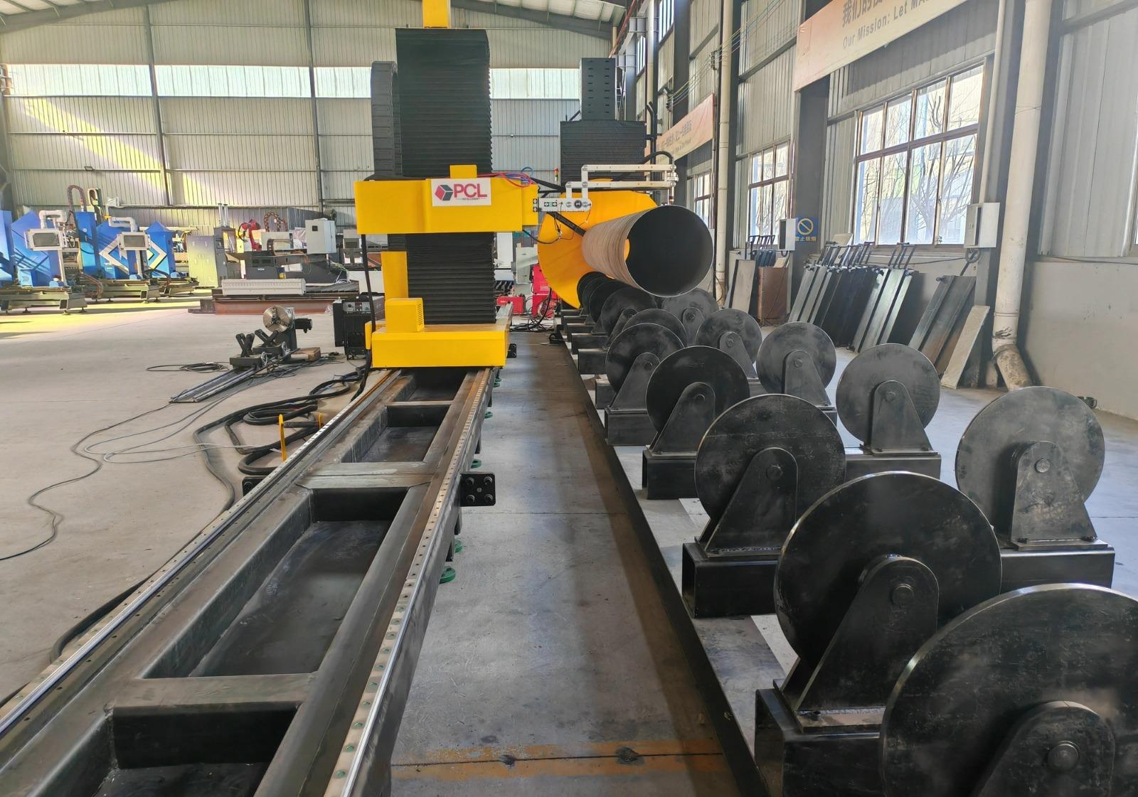
In the construction of Liquefied Natural Gas (LNG) terminals and processing facilities, structural integrity and material efficiency are the primary drivers of project profitability. The scale of these projects demands the processing of thousands of tons of structural steel, predominantly H-beams and heavy-wall piping. To meet the rigorous seismic and thermal requirements of LNG modules, the use of a Plasma Cutting Machine has become the industry standard for precision profiling and prep-work. Specifically, the introduction of zero-tailing technology has revolutionized how industrial engineers approach material yield and waste management in large-scale steel fabrication.
The Engineering Logic Behind Zero-Tailing Technology
Traditional plasma cutting processes often leave a significant “tail” or scrap portion at the end of a steel profile, usually ranging from 300mm to 800mm, depending on the clamping mechanism and the distance between the chuck and the cutting head. In the context of high-grade carbon steel or specialized alloys used in LNG supports, this waste represents a substantial financial leak. Zero-tailing technology utilizes a dual-chuck or specialized pass-through feeding system that allows the plasma torch to reach the absolute end of the raw material.
From an industrial engineering perspective, the reduction of scrap directly correlates to a lower “cost per part.” By enabling the machine to utilize the entire length of the stock material, facilities can see a material utilization increase of 5% to 8%. This is particularly critical when nesting complex geometries for pipe racks and modular skids where every centimeter of structural steel must be accounted for in the Bill of Materials (BOM).
Enhancing Intersection Accuracy for Complex Geometries
LNG projects involve intricate pipe-to-pipe and beam-to-beam intersections. The structural stability of a regasification unit or a storage tank support depends entirely on the intersection accuracy of these cuts. Any gap larger than the specified tolerance can lead to structural failure under cryogenic stress. Advanced plasma systems now utilize 8-axis or 9-axis robotic arms that calculate the 3D coordinates of an intersection in real-time, compensating for any deviations in the raw material’s flange thickness or web centering.
Kinematic Calibration and Tolerance Control
The precision of a plasma cut at an intersection is a function of kinematic calibration. For H-beams, the machine must synchronize the rotation of the beam with the lateral and vertical movement of the torch. Modern plasma systems employ laser sensing probes to map the actual surface of the steel before the arc is struck. This “scan-before-cut” workflow ensures that the intersection accuracy remains within ±0.5mm, even on beams that may have slight factory deformations or “camber.” This level of precision eliminates the need for manual grinding or secondary fit-up adjustments, streamlining the assembly line of LNG modules.
Multi-Axis Plasma Beveling for Superior Prep-Work
Weld preparation is perhaps the most time-consuming phase of structural fabrication. For the thick-walled sections required in LNG infrastructure, a simple straight cut is rarely sufficient. Multi-axis plasma heads allow for complex beveling, including V, Y, X, and K-shaped profiles. The plasma arc, when controlled by high-speed CNC processors, can maintain a consistent bevel angle even while navigating the tight radii of an H-beam’s inner fillets.
Engineers favor plasma beveling because it provides a clean, thermally optimized edge. By controlling the gas flow (usually a mix of Oxygen, Nitrogen, or H35 for stainless steel), the machine minimizes the Heat Affected Zone (HAZ). A smaller HAZ ensures that the metallurgical properties of the LNG structural steel—such as its fracture toughness at low temperatures—are not compromised during the cutting process. This is a non-negotiable requirement for offshore platforms and modular LNG units operating in Arctic or sub-zero environments.
H-Beam Processing: Engineering for Low Maintenance
High-volume production environments cannot afford frequent downtime. When processing H-beam processing tasks, the equipment is subjected to intense heat, dust, and vibration. Industrial engineers prioritize machines designed with a “low maintenance” philosophy. This involves the separation of the mechanical drive components from the cutting zone to prevent the ingress of metallic dust and slag.
Modular Torch Components and Slag Management
The latest plasma systems feature modular torch designs where consumables like nozzles, electrodes, and swirl rings can be replaced in seconds without tools. Furthermore, the integration of automated slag extraction systems ensures that the machine bed remains clear, preventing buildup that could interfere with the precision of the beam’s movement. By reducing the frequency of deep-cleaning cycles and extending the life of consumables through optimized gas-ramping technology, the operational availability of the machine often exceeds 95%.
Optimizing the Duty Cycle
The duty cycle of a plasma power source is a critical metric. for LNG Projects, where 24/7 operation is common during peak construction phases, the power supply must be rated for 100% duty cycle at maximum output. Industrial engineers select liquid-cooled torches over air-cooled variants to ensure consistent performance during long-duration cuts on heavy-gauge H-beams. This cooling prevents thermal expansion of the torch components, which is a common cause of “arc wander” and subsequent loss of cut quality.
Strategic Implementation in LNG Module Yards
The deployment of a zero-tailing plasma system in a module yard provides a measurable competitive advantage. By combining zero-tailing technology with high-speed robotic positioning, the throughput of a single fabrication cell can match that of three or four manual cutting stations. The digital integration of the CNC system with TEKLA or other structural design software allows for the direct import of XML or DSTV files, ensuring that the “as-built” structure perfectly matches the “as-designed” model.
Sustainability and Resource Efficiency
Beyond the immediate financial gains, the reduction in material waste contributes to the sustainability goals of modern energy companies. Reducing the carbon footprint of the steel supply chain—by simply wasting less of it—is an increasingly important factor in winning LNG infrastructure contracts. When the machine maximizes the nesting efficiency of every H-beam, the total energy consumed per ton of finished product decreases, aligning with global ISO standards for environmental management.
Conclusion
For the industrial engineer, the choice of a plasma cutting machine for LNG projects is a balance between precision, speed, and long-term reliability. The integration of zero-tailing technology addresses the critical need for material efficiency, while the advancement in intersection accuracy ensures the structural safety of complex cryogenic facilities. By focusing on H-beam processing systems that require minimal maintenance and offer versatile beveling capabilities, fabrication facilities can meet the most demanding project timelines without compromising on quality or safety. As the global demand for LNG continues to rise, these automated plasma solutions will remain the backbone of the structural steel industry.
-


Cantilever Welding Robot solution
-


GF laser cutting machine
-

P3015 plasma cutting machine
-

LFP3015 Fiber Laser Cutter
-

pipe plasma cutting machine
-
LFH 4020 Fiber Laser Cutting Machine
-
LFP4020
-

gantry plasma air cutting machine
-

3D robot cutting machine
-

8 axis plasma cutting machine
-

5 axis plasma cutting machine
-

LT360 tube laser cutting machine
-

robot welding workstation
-

SF6060 fiber laser cutting machine
Advanced Fiber Laser Tube Processing Technology
Our CNC Fiber Laser Tube Cutting systems revolutionize metal fabrication by integrating high-precision cutting, punching, and profiling into a single automated workflow. Designed for versatility, this technology handles a wide array of profiles including Round, Square, Rectangular, and Oval tubes, as well as complex L-shaped and U-shaped channels.
- Precision Punching: High-speed hole punching with micron-level accuracy, eliminating the need for mechanical drilling or die-stamping.
- Complex Profiling: Advanced 3D pathing allows for intricate interlocking joints and specialized notch cuts, ideal for structural frames.
- High Material Efficiency: Intelligent nesting software minimizes scrap, reducing raw material costs across large production runs.
- Clean Finish: Delivers oxide-free, burr-free edges that require zero secondary grinding before welding.

Seamlessly processing multiple profiles with consistent precision.
Global Delivery & Logistics



From our high-tech manufacturing facility directly to your global site. PCL WeldCut ensures secure packaging, professional handling, and reliable international logistics to safeguard your equipment throughout the entire journey.
One thought on “Plasma Cutting Machine with Zero-tailing technology for for LNG Projects”
Fast shipping to our facility. The setup was straightforward for our team.