Optimizing Heavy Fabrication with Zero-Tailing Plasma Technology
In the construction machinery industry, the demand for high-strength structural components requires a balance between material efficiency and mechanical precision. The transition toward Zero-tailing Plasma Cutting has redefined how heavy-duty profiles, such as H-beams, channels, and thick plates, are processed. Unlike traditional methods that leave significant material waste at the end of a workpiece, zero-tailing systems utilize advanced clamping and feeding mechanisms to ensure the plasma torch can reach the absolute edge of the material. This engineering shift directly impacts the bottom line by increasing the nesting yield per raw beam or plate.
For industrial engineers, the primary objective is the reduction of “dead zones” in the material feed. In a standard plasma setup, the distance between the chuck and the cutting head often results in 300mm to 500mm of scrap. Zero-tailing technology utilizes a dual-chuck or a pass-through synchronized movement system that allows the plasma arc to maintain stability while the workpiece is fully utilized. This capability is essential when fabricating long-reach excavator arms, crane booms, and chassis frames where high-grade steel costs are a significant portion of the total Bill of Materials (BOM).
Achieving Superior Intersection Accuracy in Complex Geometries
Construction machinery relies on the seamless joining of hollow sections and structural beams. The intersection accuracy of these components determines the overall load-bearing capacity of the machine. Plasma Cutting Machines equipped with 3D rotating heads and 5-axis motion control allow for high-precision cuts on curved surfaces and intersecting tube-to-beam joints. This is critical for the manufacturing of roll-over protective structures (ROPS) and complex lattice booms.
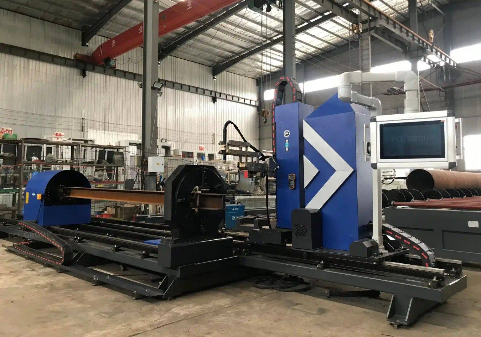
The accuracy is achieved through real-time kerf compensation and arc voltage height sensing. As the plasma torch moves across the varying geometry of an H-beam or a large diameter pipe, the system must adjust the standoff distance within milliseconds. By maintaining a constant arc length, the machine ensures that the cut angle remains perpendicular or at the precise specified bevel, preventing gaps that would otherwise require manual grinding or excessive filler material during subsequent assembly stages. The precision of these intersections ensures that structural stresses are distributed evenly across the finished assembly.
Maintenance Efficiency in H-Beam Processing
Heavy structural steel processing is inherently a harsh environment. Plasma systems are preferred in construction machinery fabrication due to their robust nature and the H-beam structural processing advantages they offer. Unlike mechanical sawing or drilling, plasma cutting is a non-contact process, which reduces the physical strain on the machine’s frame and drive systems. This leads to a significantly lower maintenance profile for the equipment.
From an industrial engineering perspective, the uptime of a plasma system is superior when handling scale and rust often found on hot-rolled H-beams. Plasma arcs are capable of piercing through surface impurities without the risk of tool breakage. Maintenance cycles are simplified into consumable management—specifically nozzles, electrodes, and shields. Modern plasma power sources now include predictive diagnostics that monitor gas flow and coolant temperature, allowing maintenance teams to perform interventions during scheduled downtimes rather than reacting to catastrophic failures on the shop floor. This reliability is vital for maintaining a continuous flow in “Just-in-Time” (JIT) manufacturing environments.
Advanced Beveling for Structural Preparation
The preparation of thick-walled segments for construction equipment requires precise edge geometries, including V, Y, K, and X bevels. Automated beveling using high-definition plasma technology eliminates the need for secondary edge milling. In the production of bulldozer blades or heavy-duty buckets, the ability to cut the profile and the bevel in a single pass is a major throughput driver.
Plasma beveling heads are engineered to compensate for the natural taper of the plasma arc. By tilting the torch and adjusting the cutting speed based on the material thickness and angle, the machine produces a weld-ready surface. This consistency is difficult to achieve with manual thermal cutting. Industrial engineers can program specific bevel profiles directly from CAD/CAM software, ensuring that every component meets the stringent tolerances required for high-stress applications. The elimination of secondary grinding not only reduces labor costs but also minimizes the heat-affected zone (HAZ) exposure for the workpiece.
Integrating Zero-Tailing into the Production Flow
The implementation of zero-tailing plasma machines requires a holistic view of the factory floor. The footprint of these machines is often more compact than traditional linear feed systems because they do not require extensive “out-feed” tables for scrap. Instead, the finished parts are pushed through, and the minimal waste is collected efficiently. This optimization of floor space allows for better material handling and ergonomics for the operators.
Furthermore, the data integration capabilities of modern plasma controllers allow for real-time tracking of material utilization. By monitoring the ratio of raw material input to finished part output, production managers can verify the ROI of zero-tailing technology. The reduction in scrap translates directly to fewer raw material orders and lower waste disposal costs, contributing to a more sustainable manufacturing process. When dealing with high-volume production of loaders and graders, these marginal gains in material yield aggregate into significant annual savings.
Technical Considerations for Arc Stability
To maximize the benefits of plasma cutting in heavy industry, the stability of the arc is paramount. Variations in gas pressure or voltage can lead to dross formation and angularity errors. High-end plasma systems used in construction machinery fabrication utilize automatic gas consoles that mix oxygen, nitrogen, and H35 (argon-hydrogen) based on the specific alloy and thickness. This level of control ensures that the cut surface is clean, minimizing the need for post-process cleaning.
The interplay between the motion control system and the plasma power supply is the heart of the machine’s performance. In zero-tailing operations, the software must manage the deceleration of the torch as it approaches the end of the material while maintaining the arc’s intensity. This ensures that the final few millimeters of the cut are as precise as the first. For engineers, this means the ability to nest parts closer together, further driving down the cost per part.
Conclusion: The Future of Plasma in Heavy Machinery
The evolution of plasma cutting toward zero-tailing and high-accuracy intersection processing represents a critical advancement for Construction Machinery manufacturers. By prioritizing material yield, reducing maintenance overhead, and automating the beveling process, companies can achieve a higher level of operational excellence. The focus remains on the structural integrity of the final product, ensured by the precision of the initial cut. As material costs continue to fluctuate, the efficiency provided by these advanced plasma systems will remain a cornerstone of competitive industrial fabrication.
-


LT240S tube laser cutting machine
-
LT120S tube laser cutting machine
-
Sale

Tank Fillet Welding Machine
Original price was: $1,000.00.$900.00Current price is: $900.00. -
Sale

MAK100 tube laser cutting machine
Original price was: $5,500.00.$5,000.00Current price is: $5,000.00. -

portable plasma air cutting machine
$1,200.00 -

2in1 fiber laser cutting machine
-

Air cooling Laser welding machine
-

HF h beam laser cutting machine
-

LT240 laser cutting machine
-

Laser welding machine
-


Cobot Welding Station
-

Gantry welding robot solution
-

Tracked Wheeled AGV Welding robot
-

LFH6020 Fiber laser cutting machine
-
LFP6020
-

robotic welidng machine
Advanced Fiber Laser Tube Processing Technology
Our CNC Fiber Laser Tube Cutting systems revolutionize metal fabrication by integrating high-precision cutting, punching, and profiling into a single automated workflow. Designed for versatility, this technology handles a wide array of profiles including Round, Square, Rectangular, and Oval tubes, as well as complex L-shaped and U-shaped channels.
- Precision Punching: High-speed hole punching with micron-level accuracy, eliminating the need for mechanical drilling or die-stamping.
- Complex Profiling: Advanced 3D pathing allows for intricate interlocking joints and specialized notch cuts, ideal for structural frames.
- High Material Efficiency: Intelligent nesting software minimizes scrap, reducing raw material costs across large production runs.
- Clean Finish: Delivers oxide-free, burr-free edges that require zero secondary grinding before welding.

Seamlessly processing multiple profiles with consistent precision.
Global Delivery & Logistics



From our high-tech manufacturing facility directly to your global site. PCL WeldCut ensures secure packaging, professional handling, and reliable international logistics to safeguard your equipment throughout the entire journey.