Optimizing Bridge Truss Fabrication via Plasma Cutting
In the field of bridge engineering, the structural integrity of a truss system depends entirely on the precision of its components. H-beams and I-beams form the backbone of these massive structures, requiring exacting tolerances for length, angle, and hole placement. The shift toward plasma cutting efficiency in heavy structural steel has enabled fabricators to meet these demands while significantly reducing operational overhead. Unlike traditional mechanical sawing or drilling, multi-axis plasma systems provide a unified solution for cutting, beveling, and marking in a single pass.
The adoption of plasma technology for Bridge Trusses is driven by the need for high-speed thermal processing that can penetrate thick-walled sections without compromising the metallurgical properties of the heat-affected zone (HAZ). Modern plasma power sources, integrated with sophisticated CNC controllers, allow for high-definition arcs that rival the finish of mechanical machining but at a fraction of the temporal cost.
Implementing Zero-Tailing Technology for Material Yield
One of the most significant cost drivers in bridge truss production is material waste. Standard structural cutting systems often leave a significant “tail” or remnant on the beam, as the clamping mechanisms require a minimum distance to maintain stability. Zero-tailing technology addresses this inefficiency through an advanced dual-chuck or multi-gripper feeding system.
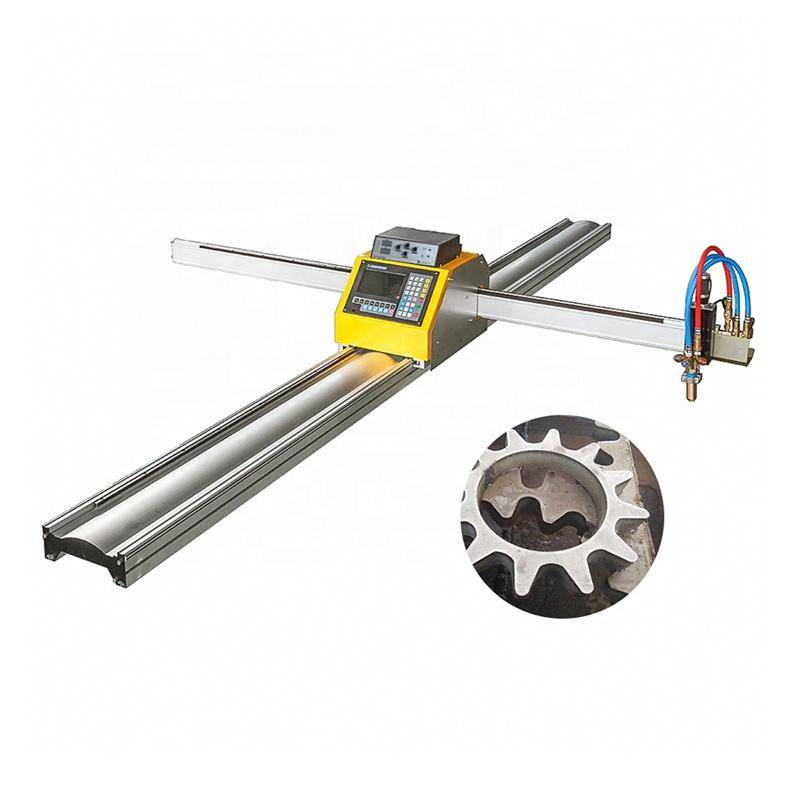
By utilizing a secondary support mechanism that engages the beam as it moves through the cutting envelope, the plasma torch can process the very end of the workpiece. This eliminates the 300mm to 600mm of scrap typically associated with H-beam processing. For a bridge project involving thousands of tons of steel, the cumulative savings from zero-tailing can reduce total material procurement costs by 3% to 5%, directly impacting the project’s bottom line.
Enhancing Intersection Accuracy in Complex Trusses
Bridge trusses often involve complex intersections where multiple diagonal members meet a horizontal chord. Achieving intersection accuracy is critical because any gap exceeding 1mm can lead to structural vulnerabilities or require excessive filler material during the joining process. Plasma Cutting Machines utilize 8-axis robotic arms or specialized gantry systems to navigate the contours of H-beams and RHS (Rectangular Hollow Sections).
The CNC system calculates the precise intersection curve, known as a cope or bird-mouth cut, accounting for the beam’s flange thickness and web radius. By using high-definition plasma, the system compensates for the kerf width in real-time. This ensures that when the diagonal member is fitted against the chord, the contact is flush across all planes. This level of precision is vital for the load-bearing requirements of suspension and cantilever bridge designs.
Plasma Beveling for Structural Integrity
Preparation for deep penetration joints is a mandatory step in bridge truss fabrication. Plasma torches equipped with rotating 3D heads allow for the creation of complex bevel profiles—including V, Y, X, and K cuts—on the edges of H-beam flanges. The ability to bevel during the initial cutting phase, rather than as a secondary manual process, ensures uniformity across all components.
The plasma arc’s ability to maintain a consistent angle at varying travel speeds is governed by the torch height control (THC) and the gas pressure regulation. For bridge trusses, where thick plates are common, the plasma system provides a clean, beveled edge that is ready for inspection. The precision of the bevel angle ensures that the subsequent assembly meets the strict geometric constraints defined in the engineering blueprints.
H-Beam Maintenance and Operational Robustness
From an industrial engineering perspective, the low maintenance of plasma systems on H-beam lines is a primary advantage. Structural steel environments are often dusty and subjected to extreme temperature fluctuations. Plasma torches are inherently robust, lacking the delicate optical components or sensitive mirrors found in other thermal processes.
The maintenance cycle for a plasma system primarily involves the replacement of consumables—nozzles, electrodes, and swirl rings. These can be swapped in minutes by a trained operator, ensuring that the machine’s uptime remains above 95%. Furthermore, the lack of mechanical force exerted on the beam (unlike sawing) means the machine’s structural frame experiences less fatigue over time, extending the capital equipment’s lifespan.
Kinematic Synchronization and Software Integration
The success of zero-tailing plasma cutting is rooted in the synchronization between the material handling system and the torch’s kinematics. Modern systems utilize TEKLA or CAD/CAM interfaces to import bridge truss designs directly. The software automatically nesting parts to maximize the zero-tailing capability.
As the beam moves through the cutting zone, the CNC coordinates the rotation of the torch with the linear feed of the beam. This eliminates the need for manual layout and marking. The plasma system can also etch part numbers and alignment marks directly onto the steel, facilitating faster assembly in the field. This digital workflow ensures that every hole and bevel is positioned according to the global coordinate system of the bridge model.
Conclusion: The Economic Impact on Infrastructure
Integrating zero-tailing plasma cutting into bridge truss production represents a fundamental shift toward lean manufacturing in the construction sector. By prioritizing bridge truss fabrication precision and reducing material waste, engineering firms can deliver safer, more cost-effective infrastructure. The combination of high intersection accuracy, the ability to handle heavy H-beams with minimal maintenance, and the versatility of multi-axis beveling makes plasma technology the optimal choice for modern structural engineering.
-


Cantilever Welding Robot solution
-


GF laser cutting machine
-

P3015 plasma cutting machine
-

LFP3015 Fiber Laser Cutter
-

pipe plasma cutting machine
-
LFH 4020 Fiber Laser Cutting Machine
-
LFP4020
-

gantry plasma air cutting machine
-

3D robot cutting machine
-

8 axis plasma cutting machine
-

5 axis plasma cutting machine
-

LT360 tube laser cutting machine
-

robot welding workstation
-

SF6060 fiber laser cutting machine
Advanced Fiber Laser Tube Processing Technology
Our CNC Fiber Laser Tube Cutting systems revolutionize metal fabrication by integrating high-precision cutting, punching, and profiling into a single automated workflow. Designed for versatility, this technology handles a wide array of profiles including Round, Square, Rectangular, and Oval tubes, as well as complex L-shaped and U-shaped channels.
- Precision Punching: High-speed hole punching with micron-level accuracy, eliminating the need for mechanical drilling or die-stamping.
- Complex Profiling: Advanced 3D pathing allows for intricate interlocking joints and specialized notch cuts, ideal for structural frames.
- High Material Efficiency: Intelligent nesting software minimizes scrap, reducing raw material costs across large production runs.
- Clean Finish: Delivers oxide-free, burr-free edges that require zero secondary grinding before welding.

Seamlessly processing multiple profiles with consistent precision.
Global Delivery & Logistics



From our high-tech manufacturing facility directly to your global site. PCL WeldCut ensures secure packaging, professional handling, and reliable international logistics to safeguard your equipment throughout the entire journey.