Optimizing Bridge Truss Fabrication with Plasma Cutting Systems
The construction of modern bridge trusses demands extreme structural integrity and material efficiency. Industrial engineers are increasingly pivoting toward advanced plasma cutting intersection accuracy to manage the complex geometries required for H-beams, I-beams, and large-scale rectangular hollow sections (RHS). In bridge engineering, the intersection of chords and web members requires high-tolerance fit-ups to ensure load distribution meets stringent safety standards.
Unlike conventional cutting methods, heavy-duty plasma systems designed for bridge components utilize multi-axis robotic heads. These systems allow for the continuous processing of structural steel, focusing on the reduction of material waste and the maximization of throughput. The transition from manual layout and torching to automated plasma profiling eliminates human error in the marking and cutting stages, which is critical when dealing with the high-strength alloys typically found in infrastructure projects.
The Mechanics of Zero-Tailing Technology
One of the most significant cost-drivers in bridge truss fabrication is material scrap. Traditional tube and beam cutting machines often leave a substantial “tailing” or remnant—the piece of steel held by the chuck that cannot be reached by the cutting head. Zero-tailing technology addresses this by utilizing a synchronized multi-chuck system.
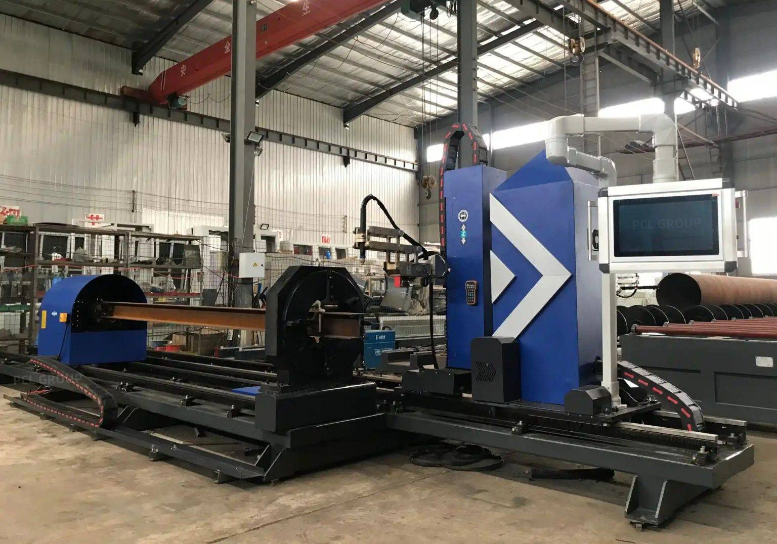
The primary chuck feeds the material forward, while a secondary, and sometimes tertiary, chuck takes over the guiding process as the material reaches the end of the stock. This handover allows the plasma torch to cut right to the edge of the raw material. In a high-volume bridge shop, reducing the tailing from 500mm to zero can save several tons of high-grade steel per project. This capability is not merely a convenience; it is a fundamental shift in the material utilization coefficient, allowing engineers to nest more parts per beam and significantly lower the cost per ton of fabricated steel.
Precision in Intersection Profiles
Bridge trusses rely on complex intersections where multiple diagonal and vertical members converge on a single chord. These joints are rarely simple 90-degree cuts. Plasma Cutting Machines equipped with 5-axis or 6-axis robotic arms are essential for generating the “saddle cuts” or “fish-mouth” profiles required for these connections.
The software driving these plasma systems calculates the intersection based on the outer diameter and wall thickness of the intersecting members. By maintaining a constant stand-off distance and adjusting the arc voltage in real-time, the machine achieves a precise fit-up. This accuracy is paramount; a gap of even a few millimeters can lead to excessive heat input during subsequent assembly, potentially compromising the metallurgical properties of the steel. The plasma arc’s ability to penetrate thick-walled H-beams (up to 50mm or more) with a focused thermal zone ensures that the geometry of the intersection remains stable.
Advanced 5-Axis Plasma Beveling for Weld Preparation
In bridge fabrication, the quality of the edge preparation determines the long-term fatigue resistance of the structure. 5-axis plasma beveling allows the cutting head to tilt and rotate, creating V, Y, K, and X-type bevels directly during the profiling process.
This eliminates the secondary operation of manual grinding or using portable beveling tools. for Bridge Trusses, where CJP (Complete Joint Penetration) welds are standard, the plasma system can be programmed to vary the bevel angle along the length of a curved intersection. This dynamic beveling ensures that the root gap and bevel angle remain consistent relative to the surface of the mating part. The result is a highly repeatable prep that meets AWS D1.5 Bridge Welding Code requirements without the labor-intensive rework associated with traditional oxy-fuel or mechanical cutting.
H-Beam Processing and Low Maintenance Requirements
H-beams are the backbone of many truss designs, but their shape presents unique challenges for thermal cutting. H-beam structural fabrication requires cutting through both the flanges and the web, often with different thicknesses and heights. Plasma cutting systems designed for this task utilize high-definition power sources that can rapidly switch parameters to handle the transition from flange to web.
From a maintenance perspective, plasma systems are exceptionally robust in the harsh environments of a steel fabrication shop. Unlike more delicate optical systems, plasma torches are designed to withstand high levels of dust, vibration, and temperature fluctuations. The primary consumables—nozzles and electrodes—are inexpensive and can be replaced in seconds. For an industrial engineer, this means higher machine uptime and lower operational expenditure (OPEX). The maintenance cycle for a heavy-duty plasma machine focuses primarily on the filtration system and the rack-and-pinion lubrication, ensuring that the machine stays in production for 20+ hours a day with minimal intervention.
Thermal Management and Heat-Affected Zone (HAZ) Control
A common concern in structural steel is the Heat-Affected Zone (HAZ) created by thermal cutting. High-definition plasma systems utilize a high-velocity gas stream (typically oxygen or nitrogen) to constrict the arc. This increases the energy density, allowing for faster travel speeds.
By increasing the cutting speed, the total heat input into the base metal is minimized, which in turn narrows the HAZ. In bridge trusses made of quenched and tempered steels, controlling the HAZ is vital to prevent local embrittlement. Modern plasma power supplies offer “fine-hole” technology and optimized gas flow to ensure that the edges remain metallurgicaly sound and ready for high-stress applications.
Integration with CAD/CAM and Industry 4.0
The efficiency of a zero-tailing plasma machine is maximized when integrated into a digital workflow. Engineers can import Tekla or Revit models directly into the machine’s nesting software. This digital thread ensures that the exact dimensions specified by the bridge designers are translated into the physical cuts.
Advanced algorithms optimize the nesting of truss members, taking full advantage of the zero-tailing hardware to place parts end-to-end. Real-time monitoring of consumable wear and gas pressures allows for predictive maintenance, further reducing the risk of unplanned downtime. By capturing data on every cut, fabricators can provide full traceability for the bridge components—a requirement that is becoming standard in public infrastructure projects globally.
Summary of Technical Advantages
The deployment of plasma cutting machines with Zero-tailing technology represents a significant leap forward in bridge truss production. By focusing on intersection accuracy and multi-axis beveling, fabricators can achieve a level of precision that reduces downstream labor costs. The rugged nature of plasma hardware ensures that these machines remain the workhorses of the structural steel industry, providing a reliable, low-maintenance solution for the most demanding engineering challenges.
-


LT240S tube laser cutting machine
-
LT120S tube laser cutting machine
-
Sale

Tank Fillet Welding Machine
Original price was: $1,000.00.$900.00Current price is: $900.00. -
Sale

MAK100 tube laser cutting machine
Original price was: $5,500.00.$5,000.00Current price is: $5,000.00. -

portable plasma air cutting machine
$1,200.00 -

2in1 fiber laser cutting machine
-

Air cooling Laser welding machine
-

HF h beam laser cutting machine
-

LT240 laser cutting machine
-

Laser welding machine
-


Cobot Welding Station
-

Gantry welding robot solution
-

Tracked Wheeled AGV Welding robot
-

LFH6020 Fiber laser cutting machine
-
LFP6020
-

robotic welidng machine
Advanced Fiber Laser Tube Processing Technology
Our CNC Fiber Laser Tube Cutting systems revolutionize metal fabrication by integrating high-precision cutting, punching, and profiling into a single automated workflow. Designed for versatility, this technology handles a wide array of profiles including Round, Square, Rectangular, and Oval tubes, as well as complex L-shaped and U-shaped channels.
- Precision Punching: High-speed hole punching with micron-level accuracy, eliminating the need for mechanical drilling or die-stamping.
- Complex Profiling: Advanced 3D pathing allows for intricate interlocking joints and specialized notch cuts, ideal for structural frames.
- High Material Efficiency: Intelligent nesting software minimizes scrap, reducing raw material costs across large production runs.
- Clean Finish: Delivers oxide-free, burr-free edges that require zero secondary grinding before welding.

Seamlessly processing multiple profiles with consistent precision.
Global Delivery & Logistics



From our high-tech manufacturing facility directly to your global site. PCL WeldCut ensures secure packaging, professional handling, and reliable international logistics to safeguard your equipment throughout the entire journey.