Optimizing Bridge Truss Fabrication with Zero-Tailing Plasma Technology
In the field of structural engineering, the production of bridge trusses demands a rigorous adherence to dimensional tolerances and material efficiency. Traditional thermal cutting processes often result in significant remnants, known as “tails,” which represent a direct loss in material yield. The implementation of Zero-tailing technology addresses this inefficiency by utilizing advanced chucking systems that allow the plasma torch to operate across the entire length of the raw profile, including the final section of the beam. For bridge components where H-beams and heavy channels are standard, this technology ensures that the raw material is utilized to its maximum potential, reducing scrap rates by up to 15% per profile.
Mechanical Advantages of Zero-Tailing Systems
The engineering behind zero-tailing involves a multi-chuck configuration. Unlike standard machines that require a minimum distance between the chuck and the cutting head for safety and mechanical clearance, zero-tailing systems employ a “passing” or “shifting” chuck mechanism. This allows the beam to be moved through the cutting zone even when the remaining stock is minimal. In the context of bridge trusses—which often require chord members exceeding 12 meters—the ability to utilize the final 500mm of a beam translates to substantial cost savings across an entire project. This mechanical capability is essential for industrial engineers focused on lean manufacturing principles and the reduction of Work-in-Process (WIP) inventory.
Precision Intersection Accuracy in Complex Truss Nodes
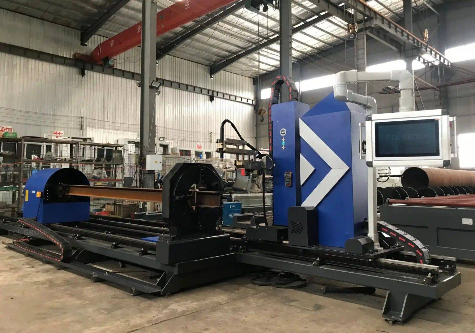
Bridge trusses are characterized by complex nodes where multiple diagonal and vertical members intersect the main chords. The Plasma Cutting accuracy required for these intersections is critical for the load-bearing capacity of the structure. Modern plasma systems utilize high-definition power sources and five-axis robotic heads to execute precise cope cuts and intersections. These systems calculate the kerf compensation in real-time, ensuring that the physical cut matches the CAD/CAM model within a fraction of a millimeter.
Kerf Compensation and Path Optimization
Thermal cutting naturally involves a kerf width—the amount of material removed by the plasma arc. Industrial engineers must calibrate these machines to account for arc voltage, gas pressure, and nozzle wear. By integrating CNC control with real-time feedback, the plasma system maintains a consistent arc length, which is vital for maintaining verticality on thick-walled H-beams. In bridge truss applications, where gaps in intersections can lead to structural failure or excessive weld filler usage, achieving high intersection accuracy is non-negotiable. The plasma arc is stabilized through secondary shielding gases, which constricts the arc and increases energy density, resulting in a cleaner, narrower kerf.
3D Profile Cutting and Spatial Alignment
The intersection of an H-beam with another structural member often requires a non-linear cut path. Plasma Cutting Machines equipped with 3D rotation capabilities can navigate the flanges and webs of a beam in a single continuous movement. This eliminates the need for manual layout and manual cutting, which are prone to human error. From an industrial engineering perspective, the reduction in handling time and the elimination of template-based marking significantly increase the Overall Equipment Effectiveness (OEE) of the fabrication line.
H-Beam Processing and Low Maintenance Requirements
H-beams are the backbone of modern bridge design, offering high moments of inertia. Processing these sections using plasma technology provides a distinct advantage in terms of H-beam structural integrity. Unlike mechanical shearing or punching, plasma cutting is a non-contact process that does not introduce mechanical stress or micro-cracking into the base metal. Furthermore, the maintenance profile of plasma systems is optimized for heavy industrial environments where dust and heat are prevalent.
Durability of Plasma Components
Industrial plasma systems are designed for high duty cycles. The consumables—nozzles, electrodes, and swirl rings—are engineered for rapid replacement, minimizing downtime. In a bridge fabrication facility, the robustness of the plasma torch is a key factor in operational continuity. The lack of sensitive optical components found in other thermal processes means that plasma machines are less susceptible to the vibrations and particulate matter common in heavy steel workshops. This low-maintenance characteristic ensures that the machine remains operational during peak production phases of large infrastructure projects.
Optimizing Consumable Life Cycles
To further reduce operating costs, engineers monitor the “arc-on” time versus the consumable wear. Advanced gas consoles automatically adjust flow rates during the pierce and cut phases to extend the life of the electrode. For thick H-beam flanges, the use of oxygen-plasma or nitrogen-shielding can produce a metallurgical edge quality that requires minimal grinding before the next stage of fabrication. This efficiency in the cutting stage directly impacts the downstream throughput of the assembly area.
Advanced Beveling for High-Strength Joints
Bridge trusses rely on full-penetration butt joints to transfer loads between members. Achieving the correct bevel angle is paramount for the structural performance of the weldment. Beveling efficiency in plasma cutting allows for the creation of V, Y, X, and K-shaped bevels directly on the cutting table. The ability to bevel the edges of thick-walled sections during the initial profile cutting phase removes a massive bottleneck in the production flow.
Consistency in Bevel Angles
A robotic plasma head can maintain a precise angle relative to the material surface, even when navigating the transition between the web and the flange of an H-beam. This consistency is vital for robotic welding processes that follow the cutting stage. If the bevel angle fluctuates, the weld volume changes, leading to inconsistencies in heat input and potential distortion. Plasma systems provide a repeatable, high-speed solution for preparing edges on high-tensile bridge steels, ensuring that the fit-up is tight and the joint geometry meets international structural codes.
Thermal Management and Edge Quality
While plasma is a thermal process, modern high-definition systems manage the Heat Affected Zone (HAZ) through precise speed control and water-cooled torches. For bridge steels, minimizing the HAZ is important to maintain the original material properties of the alloy. The high cutting speeds achievable with plasma reduce the total heat input into the part, preventing the warping of long truss members. This thermal control ensures that the final assembly meets the strict camber and sweep requirements specified in bridge engineering designs.
Conclusion: Integrated Engineering Value
The transition to zero-tailing plasma cutting machines represents a strategic shift in bridge truss manufacturing. By focusing on the intersection of material science and mechanical precision, industrial engineers can deliver projects that are both cost-effective and structurally superior. The combination of Zero-tailing technology for material conservation, high-precision intersection capabilities for complex nodes, and robust, low-maintenance hardware for H-beam processing creates a highly efficient production environment. As infrastructure requirements continue to demand larger spans and higher load capacities, the role of precision plasma cutting in ensuring the integrity and efficiency of structural steel fabrication remains indispensable.
-


LT240S tube laser cutting machine
-
LT120S tube laser cutting machine
-
Sale

Tank Fillet Welding Machine
Original price was: $1,000.00.$900.00Current price is: $900.00. -
Sale

MAK100 tube laser cutting machine
Original price was: $5,500.00.$5,000.00Current price is: $5,000.00. -

portable plasma air cutting machine
$1,200.00 -

2in1 fiber laser cutting machine
-

Air cooling Laser welding machine
-

HF h beam laser cutting machine
-

LT240 laser cutting machine
-

Laser welding machine
-


Cobot Welding Station
-

Gantry welding robot solution
-

Tracked Wheeled AGV Welding robot
-

LFH6020 Fiber laser cutting machine
-
LFP6020
-

robotic welidng machine
Advanced Fiber Laser Tube Processing Technology
Our CNC Fiber Laser Tube Cutting systems revolutionize metal fabrication by integrating high-precision cutting, punching, and profiling into a single automated workflow. Designed for versatility, this technology handles a wide array of profiles including Round, Square, Rectangular, and Oval tubes, as well as complex L-shaped and U-shaped channels.
- Precision Punching: High-speed hole punching with micron-level accuracy, eliminating the need for mechanical drilling or die-stamping.
- Complex Profiling: Advanced 3D pathing allows for intricate interlocking joints and specialized notch cuts, ideal for structural frames.
- High Material Efficiency: Intelligent nesting software minimizes scrap, reducing raw material costs across large production runs.
- Clean Finish: Delivers oxide-free, burr-free edges that require zero secondary grinding before welding.

Seamlessly processing multiple profiles with consistent precision.
Global Delivery & Logistics



From our high-tech manufacturing facility directly to your global site. PCL WeldCut ensures secure packaging, professional handling, and reliable international logistics to safeguard your equipment throughout the entire journey.