Optimizing Bridge Truss Fabrication via Zero-Tailing Plasma Systems
In the realm of structural engineering, the bridge truss represents one of the most demanding applications for steel fabrication. These structures require absolute fidelity to CAD models to ensure load distribution meets safety factors. The introduction of zero-tailing Plasma Cutting technology has transformed the workflow by addressing the primary bottleneck in heavy-duty manufacturing: material yield and joint preparation. Industrial engineers are increasingly pivoting toward high-definition plasma systems that utilize multi-axis robotic arms to handle thick-walled H-beams and rectangular hollow sections (RHS) with surgical precision.
Traditional thermal cutting often leaves significant scrap at the leading and trailing ends of a beam due to the mechanical limitations of clamping carriages. Zero-tailing technology employs a dual-chuck or synchronized feeding mechanism that allows the plasma torch to access the extreme ends of the workpiece. This capability translates to a 10% to 15% reduction in raw material costs, a critical margin when dealing with high-grade structural steel used in bridge construction.
Mechanical Advantages of Plasma Intersection Accuracy
The integrity of a bridge truss depends on the fit-up of its members. When chords and diagonals meet, the intersection geometry is often complex, requiring non-linear cuts across both flanges and webs. Plasma Cutting Machines equipped with 8-axis motion control can execute these intersections with an accuracy tolerance of +/- 0.5mm. This level of intersection accuracy is vital for ensuring that the stress is transferred correctly across the joint without inducing local eccentricities.
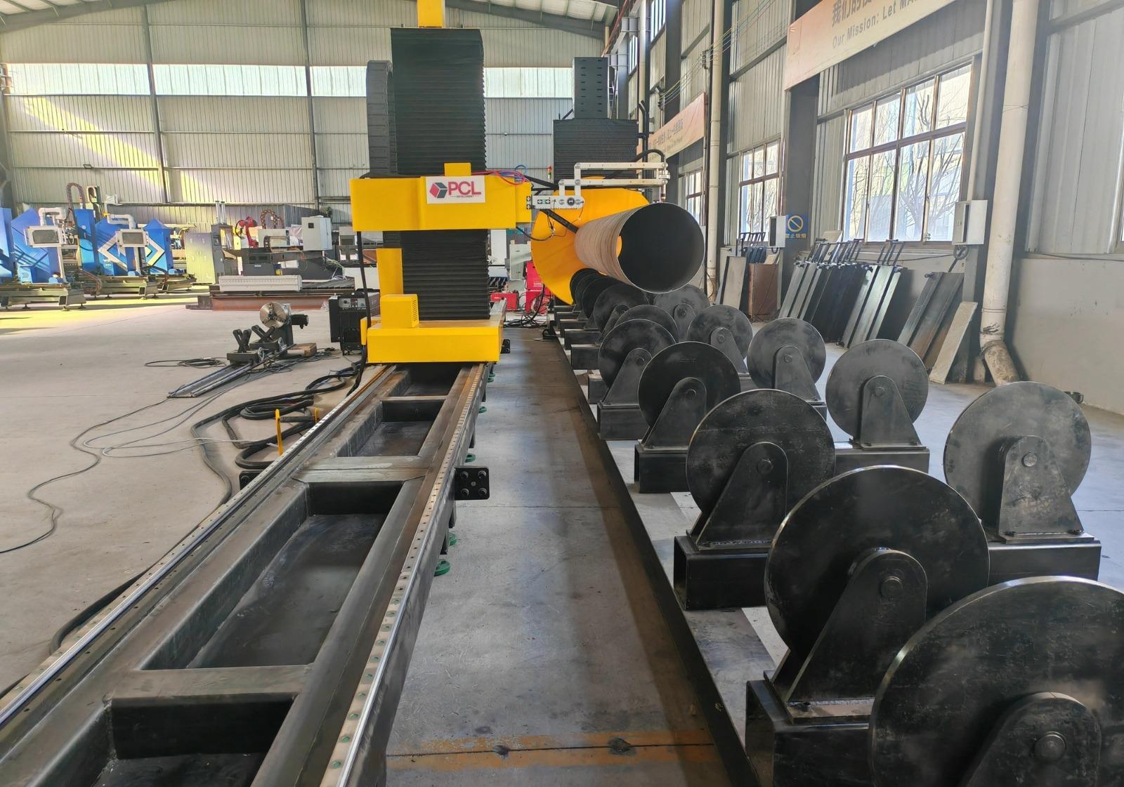
High-definition plasma power sources maintain a constricted arc, which minimizes the heat-affected zone (HAZ). for Bridge Trusses, a smaller HAZ is preferable as it preserves the metallurgical properties of the base metal, reducing the risk of embrittlement near the connection points. The software governing these cuts uses advanced nesting algorithms that account for the kerf width of the plasma stream, ensuring that even the most intricate “bird-mouth” cuts for pipe-to-beam intersections require no manual grinding before assembly.
H-Beam Processing and Low Maintenance Operations
H-beams serve as the backbone of many bridge designs, but their physical profile presents challenges for automated cutting. Plasma systems are uniquely suited for this environment due to their robust nature. Unlike more sensitive optical systems, plasma torches are resilient against the dust, scale, and vibration inherent in heavy structural shops. This leads to a H-beam low maintenance profile that maximizes machine uptime.
Consumable Management and Durability
From an industrial engineering perspective, the Total Cost of Ownership (TCO) is a primary metric. Plasma systems facilitate this through simplified consumable paths. Modern electrode and nozzle designs utilize liquid cooling to extend life cycles, even when piercing 50mm plate or beam webs. Because the plasma process is a chemical-thermal reaction involving ionized gas, the torch head can be positioned with a significant standoff distance, protecting the machine’s motion components from molten spatter and slag.
Environmental Resilience
Bridge fabrication yards are often semi-enclosed environments prone to temperature fluctuations and airborne particulates. The mechanical drive systems of modern plasma cutters are designed with shielded rack-and-pinion or ball screw assemblies. This ensures that the high-speed positioning required for H-beam flange stripping and web penetration remains consistent over thousands of duty cycles without requiring the clean-room conditions demanded by alternative thermal processes.
Advanced Beveling for High-Strength Joints
Bridge components rarely utilize simple square-edge cuts. To facilitate full-penetration welds that can withstand cyclic loading and vibration, structural members must be prepped with specific bevel profiles. Plasma beveling technology allows for the simultaneous cutting and chamfering of edges, including V, X, Y, and K-shaped preparations.
The integration of a robotic bevel head allows the plasma arc to tilt up to 45 or 50 degrees. This eliminates the need for secondary beveling via manual torches or track cutters, which are prone to human error and inconsistency. In a bridge truss, where hundreds of diagonal braces must be beveled to match the curvature or angle of the main chord, the speed of automated plasma beveling reduces the total fabrication lead time by approximately 30%.
Consistency in Weld Prep Geometry
By utilizing a 5-axis or 6-axis bevel head, the machine compensates for the natural “tilt and turn” of the beam geometry. The sensor systems dynamically track the surface of the steel, adjusting the torch height in real-time to maintain a constant arc voltage. This results in a uniform bevel face across the entire length of the cut, which is essential for automated welding robots that may follow in the production line.
Zero-Tailing Logic: Engineering the Material Flow
The logic behind zero-tailing involves a sophisticated interplay between the material handling conveyor and the cutting head. Traditionally, a “dead zone” of several hundred millimeters existed at the end of each beam because the machine’s grippers needed a surface to hold. Modern zero-tailing machines solve this by using a pass-through chuck system or a dual-carriage design where one gripper takes over as the other releases.
This allows for the fabrication of “short pieces”—such as gusset plates or small truss reinforcements—directly from the tail end of a primary beam. For a project manager overseeing a bridge contract, this means the bill of materials (BOM) can be squeezed for maximum efficiency. Every millimeter of the H-beam is accessible, turning what was once “drop” into usable structural components.
Operational Throughput and System Integration
Integrating a zero-tailing plasma machine into a bridge production line requires a focus on data flow. Modern systems accept direct inputs from TEKLA or other structural BIM software. The machine interprets the DSTV files, automatically calculating the most efficient path for 8-axis movement. This digital-to-physical workflow removes the draftsman’s interpretation error from the shop floor.
The throughput gains are realized not just in the cutting speed—which for 20mm steel can exceed 2000mm/min—but in the reduction of handling. A single plasma cell can perform the work of a band saw, a drill line, and a manual beveling station. By consolidating these functions, the industrial engineer reduces the footprint of the fabrication line and minimizes the overhead associated with moving heavy beams between work cells via overhead cranes.
Technical Conclusion
For the construction of modern bridge trusses, the reliance on high-precision plasma technology is no longer optional. The synergy between zero-tailing mechanics and multi-axis intersection accuracy provides a competitive edge in both material utilization and structural reliability. By prioritizing low-maintenance H-beam processing and automated beveling, facilities can achieve a higher output per square foot of floor space while maintaining the rigorous quality standards required for public infrastructure projects. The focus remains on the arc: a robust, reliable, and highly accurate tool for shaping the future of heavy industry.
-


Cantilever Welding Robot solution
-


GF laser cutting machine
-

P3015 plasma cutting machine
-

LFP3015 Fiber Laser Cutter
-

pipe plasma cutting machine
-
LFH 4020 Fiber Laser Cutting Machine
-
LFP4020
-

gantry plasma air cutting machine
-

3D robot cutting machine
-

8 axis plasma cutting machine
-

5 axis plasma cutting machine
-

LT360 tube laser cutting machine
-

robot welding workstation
-

SF6060 fiber laser cutting machine
Advanced Fiber Laser Tube Processing Technology
Our CNC Fiber Laser Tube Cutting systems revolutionize metal fabrication by integrating high-precision cutting, punching, and profiling into a single automated workflow. Designed for versatility, this technology handles a wide array of profiles including Round, Square, Rectangular, and Oval tubes, as well as complex L-shaped and U-shaped channels.
- Precision Punching: High-speed hole punching with micron-level accuracy, eliminating the need for mechanical drilling or die-stamping.
- Complex Profiling: Advanced 3D pathing allows for intricate interlocking joints and specialized notch cuts, ideal for structural frames.
- High Material Efficiency: Intelligent nesting software minimizes scrap, reducing raw material costs across large production runs.
- Clean Finish: Delivers oxide-free, burr-free edges that require zero secondary grinding before welding.

Seamlessly processing multiple profiles with consistent precision.
Global Delivery & Logistics



From our high-tech manufacturing facility directly to your global site. PCL WeldCut ensures secure packaging, professional handling, and reliable international logistics to safeguard your equipment throughout the entire journey.