Optimization of Thermal Cutting in Oil and Gas Infrastructure
In the heavy fabrication sector, specifically within the production of oil and gas storage tanks, the shift toward automated Plasma Cutting systems is driven by the need for high-velocity throughput and tight dimensional tolerances. Unlike general-purpose machinery, plasma cutting systems designed for this environment must handle thick carbon steel and stainless steel plates while maintaining edge quality that meets ISO 9013 standards. The engineering objective is to eliminate manual layout processes and minimize post-cut grinding, which traditionally consumes up to 30% of total fabrication time.
Structural Integrity: The H-Beam Gantry Advantage
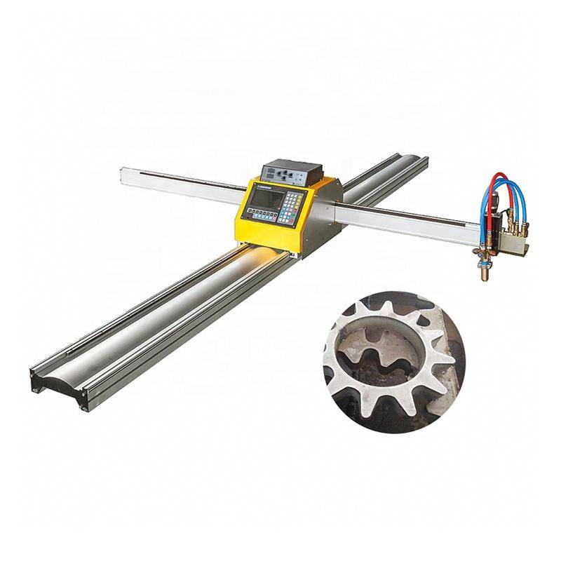
From a mechanical engineering perspective, the stability of the motion platform is the primary determinant of long-term accuracy. Heavy-duty plasma systems utilize a reinforced H-beam gantry structure. This design provides a high strength-to-weight ratio, which is critical for damping the vibrations generated during high-speed directional changes of the torch carriage.
Low Maintenance and Rigidity
The H-beam configuration facilitates a low center of gravity for the dual-drive motors. By utilizing oversized linear bearings and helical rack-and-pinion systems, the machine achieves superior positioning accuracy. For an industrial engineer, this translates to low maintenance cycles. Unlike cantilever designs that are prone to deflection at the arm’s extremity, the H-beam bridge ensures the torch remains perpendicular to the workpiece across the entire transverse span. This rigidity is essential when processing the large-format plates required for tank shells, where even a 0.5mm deviation can lead to significant alignment issues during the rolling and fit-up stages.
Precision Intersection Cutting for Nozzles and Manways
Oil and gas tanks require numerous penetrations for nozzles, manways, and instrumentation ports. The geometry of these intersections—where a cylindrical nozzle meets a curved tank wall—is mathematically complex. Achieving high intersection accuracy is where advanced plasma systems provide the highest ROI.
Kinematic Coordination
When cutting a hole for a nozzle on a dished head or a cylindrical shell, the plasma torch must simultaneously manage three linear axes (X, Y, Z) and two rotational axes (A, B). The system’s controller calculates the varying bevel angle required along the cut path to ensure a constant root gap for subsequent welding. If the intersection is not precise, the resulting gaps require excessive filler metal, increasing the risk of thermal distortion and hydrogen cracking in the heat-affected zone (HAZ). High-definition plasma power sources, combined with precise gas metering, allow for narrow kerf widths that maintain the structural integrity of the shell.
Multi-Axis Beveling for Weld Preparation
Weld preparation is a critical bottleneck in tank fabrication. Manual beveling with hand-held torches or grinders is inconsistent and labor-intensive. Modern plasma machines equipped with 5-axis bevel heads automate this process entirely.
V, Y, and X-Cut Capabilities
The ability to perform beveling in a single pass is a significant force multiplier. For thick-walled pressure vessels, a “V” or “Y” bevel is often required to ensure full penetration. The plasma system’s software modulates the cutting speed and gas pressure in real-time as the torch tilts. This prevents the “rounding” of top edges and maintains the sharpness of the root face. By delivering a weld-ready edge directly from the cutting table, the facility can bypass the secondary processing station, effectively shortening the production lead time for a standard 50,000-barrel tank by several days.
Offline Programming and Simulation Workflow
To maximize the “green-light time” of the plasma machine, the transition to offline programming (OLP) is mandatory. OLP allows engineers to prepare nests and generate G-code on a separate workstation while the machine is actively cutting.
Eliminating Machine Downtime
In an OLP environment, the industrial engineer imports CAD models of the tank components directly into the CAM software. The software then performs 3D nesting to maximize material utilization. More importantly, the OLP system includes a full digital twin of the plasma machine. This enables the simulation of the cut path to identify potential collisions between the torch head and the workpiece or fixtures.
G-Code Optimization
Advanced OLP tools optimize the lead-in and lead-out points to prevent divots in the finished part. For oil and gas applications, where material traceability is paramount, the OLP software can also integrate with ERP systems to track heat numbers and remnant inventory. This data-driven approach ensures that the cutting parameters are optimized for specific plate thicknesses and material grades before the first spark is even struck.
Thermal Management and Material Stability
Plasma cutting is a high-heat process. Managing the thermal expansion of large plates is a specific challenge in tank fabrication. Industrial engineers must implement strategic cutting sequences, often programmed via OLP, to distribute heat evenly across the plate.
Underwater vs. Downdraft Tables
The choice of cutting table also impacts the accuracy. Water tables can help in cooling the material quickly, reducing the overall thermal envelope and minimizing warping. However, for high-alloy steels used in specialized gas storage, high-volume downdraft systems are often preferred to maintain the chemical properties of the edge. By controlling the thermal environment, the machine ensures that the final dimensions of the tank segments remain within the strict tolerances required for automated girth welding.
Conclusion: Quantifiable Efficiency in Heavy Fabrication
The integration of a high-definition plasma cutting system with an H-beam gantry and OLP capabilities represents a fundamental shift in oil and gas tank manufacturing. The focus on intersection accuracy and multi-axis beveling addresses the primary cost drivers in the industry: labor and material waste. By utilizing a rigid mechanical platform and sophisticated simulation software, manufacturers can achieve a level of repeatability that manual processes cannot match. The result is a streamlined production flow where every cut component fits perfectly into the final assembly, ensuring the structural integrity and safety of the storage infrastructure.
-


LT240S tube laser cutting machine
-
LT120S tube laser cutting machine
-
Sale

Tank Fillet Welding Machine
Original price was: $1,000.00.$900.00Current price is: $900.00. -
Sale

MAK100 tube laser cutting machine
Original price was: $5,500.00.$5,000.00Current price is: $5,000.00. -

portable plasma air cutting machine
$1,200.00 -

2in1 fiber laser cutting machine
-

Air cooling Laser welding machine
-

HF h beam laser cutting machine
-

LT240 laser cutting machine
-

Laser welding machine
-


Cobot Welding Station
-

Gantry welding robot solution
-

Tracked Wheeled AGV Welding robot
-

LFH6020 Fiber laser cutting machine
-
LFP6020
-

robotic welidng machine
Advanced Fiber Laser Tube Processing Technology
Our CNC Fiber Laser Tube Cutting systems revolutionize metal fabrication by integrating high-precision cutting, punching, and profiling into a single automated workflow. Designed for versatility, this technology handles a wide array of profiles including Round, Square, Rectangular, and Oval tubes, as well as complex L-shaped and U-shaped channels.
- Precision Punching: High-speed hole punching with micron-level accuracy, eliminating the need for mechanical drilling or die-stamping.
- Complex Profiling: Advanced 3D pathing allows for intricate interlocking joints and specialized notch cuts, ideal for structural frames.
- High Material Efficiency: Intelligent nesting software minimizes scrap, reducing raw material costs across large production runs.
- Clean Finish: Delivers oxide-free, burr-free edges that require zero secondary grinding before welding.

Seamlessly processing multiple profiles with consistent precision.
Global Delivery & Logistics



From our high-tech manufacturing facility directly to your global site. PCL WeldCut ensures secure packaging, professional handling, and reliable international logistics to safeguard your equipment throughout the entire journey.