Optimizing Wind Tower Fabrication via Advanced Plasma Systems
In the rigorous landscape of renewable energy infrastructure, the production of wind towers demands extreme precision and structural reliability. The primary tool for managing the massive steel plates—often exceeding 50mm in thickness—is the heavy-duty Plasma Cutting Machine. Unlike standard fabrication tools, these systems must operate under high duty cycles while maintaining tight tolerances over plate lengths that can exceed 30 meters. The engineering challenge lies in managing heat distortion while ensuring that the geometric dimensions of the tower segments remain within sub-millimeter specifications.
The Role of Arc Voltage Control (AVC) in Precision Cutting
One of the most critical components in modern plasma systems is arc voltage control. In wind tower fabrication, plates are rarely perfectly flat across their entire surface area. Even a minor deviation in plate height can lead to catastrophic failure in cut quality or damage to the torch consumables. AVC functions as a real-time feedback loop. It measures the voltage between the plasma torch electrode and the workpiece; since this voltage is directly proportional to the distance of the arc gap, the system can modulate the Z-axis height instantaneously.
For an industrial engineer, the implementation of AVC means a significant reduction in scrap rates. By maintaining a constant standoff distance, the machine ensures a consistent kerf width. This consistency is vital for the downstream fit-up of tower sections. Without AVC, the variations in height would cause the arc to widen or narrow, resulting in dross accumulation and angular deviation that would require expensive manual grinding.
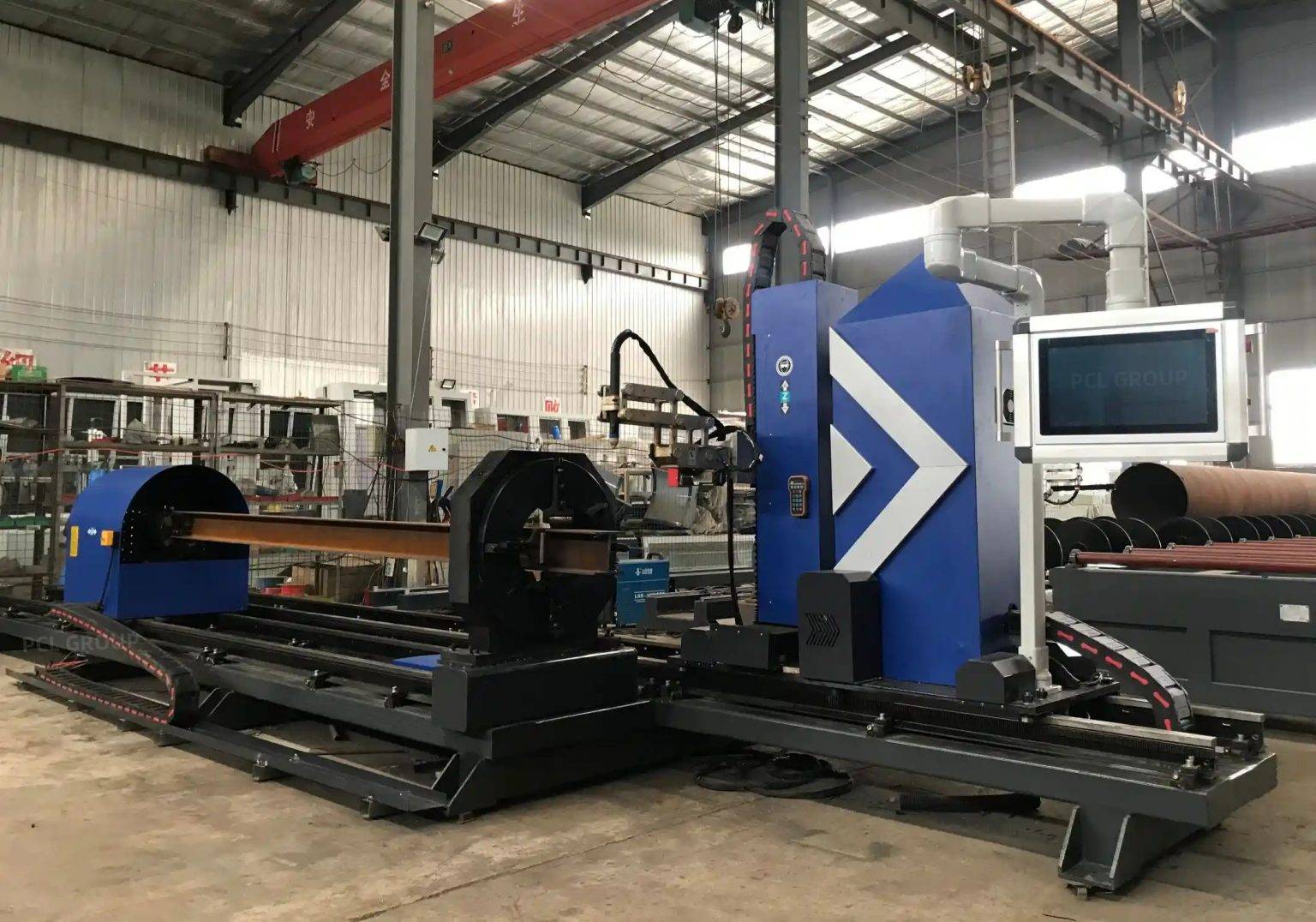
Achieving Complex Intersection Accuracy
Wind towers are not simple cylinders; they require complex cutouts for access doors, cable entries, and internal platform supports. The wind tower fabrication process relies on the plasma machine’s ability to execute intersection cuts where curved surfaces meet. Precision in these intersections is non-negotiable because the structural load of the entire turbine assembly rests on the integrity of these joints.
Geometric Calibration and Path Planning
High-definition plasma systems utilize advanced CNC algorithms to compensate for the “arc lead” and “lag” that occurs during high-speed directional changes. When cutting the door frames of a tower, the software must calculate the exact intersection of a 3D cylindrical plane. The plasma torch, guided by AVC, follows this path while adjusting its angle to maintain a perpendicular or specific beveled edge relative to the tangent of the curve. This level of intersection accuracy ensures that the inserted door frames fit with zero-gap tolerance, facilitating a faster assembly process.
Multi-Axis Beveling for Weld Preparation
The thickness of wind tower shells necessitates specialized edge preparation. Automated beveling heads on plasma machines allow for the creation of V, X, K, and Y-shaped profiles in a single pass. This is a massive leap in efficiency over traditional oxy-fuel or mechanical edge milling.
Thermal Management and Edge Quality
Plasma beveling provides a narrow heat-affected zone (HAZ), which is critical for maintaining the metallurgical properties of the high-tensile steel used in towers. By utilizing high-flow gas shields and precise current modulation, the plasma machine delivers a clean, oxide-free surface. This cleanliness is essential for the integrity of the subsequent bonding processes, as it prevents inclusions and porosity. The ability to switch from a straight cut to a 45-degree bevel mid-program allows for a continuous workflow, eliminating the need to move the massive plates between different workstations.
H-Beam Processing and Low Maintenance Requirements
While the tower shell is the most visible component, the internal skeleton often consists of H-beams and structural profiles that support platforms and ladder systems. Integrating plasma cutting for these H-beams offers a distinct advantage in terms of maintenance and uptime. Mechanical drills and saws involve consumable blades and cooling fluids that require frequent replacement and cleaning.
Comparison of Mechanical vs. Plasma Maintenance
Plasma systems for H-beam processing are characterized by their non-contact nature. Aside from the electrode and nozzle—which are designed for rapid “plug-and-play” replacement—the machine has few moving parts subject to friction-based wear. This “low maintenance” profile is highly attractive in high-volume production environments where machine downtime can cost thousands of dollars per hour. The plasma arc effortlessly slices through flange and web sections, regardless of material hardness, ensuring that the internal supports are produced as efficiently as the outer shell segments.
System Integration and Throughput Optimization
From an Industrial Engineering perspective, the plasma cutting machine is the “pacemaker” of the fabrication facility. To optimize throughput, these machines are often integrated into a wider material handling system. Automated loading tables and conveyor systems move the plates into position, where the plasma gantry—equipped with AVC and beveling heads—begins the sequence.
By focusing on automated beveling and high-speed plasma gas mixtures (such as Oxygen-Air or Argon-Hydrogen), manufacturers can push the limits of linear cutting speeds. Modern power sources now offer 100% duty cycles, meaning the machine can run 24/7 without cooling breaks. This is essential for the wind energy sector, where project timelines are often compressed and the demand for tower components is seasonal and intense.
Conclusion: The Strategic Value of Plasma Technology
In summary, the application of plasma cutting technology in wind tower fabrication is not merely about “cutting metal.” It is about a sophisticated synergy of electrical engineering (Arc Voltage Control), mechanical precision (Multi-axis Beveling), and software intelligence (Intersection Accuracy). By choosing plasma over slower, high-maintenance mechanical alternatives, fabrication plants achieve a lower cost-per-part and higher structural reliability. The focus on low maintenance for structural H-beams further ensures that the facility remains operational with minimal intervention, solidifying plasma’s role as the indispensable tool in the global transition to sustainable wind energy.
-


LT240S tube laser cutting machine
-
LT120S tube laser cutting machine
-
Sale

Tank Fillet Welding Machine
Original price was: $1,000.00.$900.00Current price is: $900.00. -
Sale

MAK100 tube laser cutting machine
Original price was: $5,500.00.$5,000.00Current price is: $5,000.00. -

portable plasma air cutting machine
$1,200.00 -

2in1 fiber laser cutting machine
-

Air cooling Laser welding machine
-

HF h beam laser cutting machine
-

LT240 laser cutting machine
-

Laser welding machine
-


Cobot Welding Station
-

Gantry welding robot solution
-

Tracked Wheeled AGV Welding robot
-

LFH6020 Fiber laser cutting machine
-
LFP6020
-

robotic welidng machine
Advanced Fiber Laser Tube Processing Technology
Our CNC Fiber Laser Tube Cutting systems revolutionize metal fabrication by integrating high-precision cutting, punching, and profiling into a single automated workflow. Designed for versatility, this technology handles a wide array of profiles including Round, Square, Rectangular, and Oval tubes, as well as complex L-shaped and U-shaped channels.
- Precision Punching: High-speed hole punching with micron-level accuracy, eliminating the need for mechanical drilling or die-stamping.
- Complex Profiling: Advanced 3D pathing allows for intricate interlocking joints and specialized notch cuts, ideal for structural frames.
- High Material Efficiency: Intelligent nesting software minimizes scrap, reducing raw material costs across large production runs.
- Clean Finish: Delivers oxide-free, burr-free edges that require zero secondary grinding before welding.

Seamlessly processing multiple profiles with consistent precision.
Global Delivery & Logistics



From our high-tech manufacturing facility directly to your global site. PCL WeldCut ensures secure packaging, professional handling, and reliable international logistics to safeguard your equipment throughout the entire journey.