Precision Plasma Cutting and Arc Voltage Control in Structural Fabrication
The fabrication of structural steel, particularly for large-scale infrastructure and industrial buildings, demands high-speed thermal cutting solutions that do not compromise on dimensional integrity. High-definition plasma cutting has emerged as the primary tool for processing heavy sections, such as H-beams, I-beams, and thick plate steel. Unlike manual or basic mechanized processes, modern plasma systems utilize Arc Voltage Control to maintain a consistent distance between the torch tip and the workpiece, a critical factor when dealing with the inherent surface irregularities and material warping common in hot-rolled steel.
Industrial engineers prioritize plasma systems because they balance capital expenditure with high operational uptime. By focusing on the physics of the plasma arc and the mechanical stability of the gantry or robotic arm, manufacturers can achieve tolerances that were previously only possible through secondary machining. This analysis focuses on the technical variables of arc voltage, the geometry of intersections, and the long-term maintenance cycles of these robust systems.
The Mechanism of Arc Voltage Control (AVC)
Arc Voltage Control is an automated feedback loop that monitors the electrical potential between the plasma torch electrode and the metal plate. In a plasma system, the voltage is directly proportional to the length of the arc. As the distance between the torch and the material increases, the voltage rises; as the distance decreases, the voltage drops. The AVC system continuously samples this voltage at millisecond intervals and adjusts the Z-axis motor to maintain a preset value.
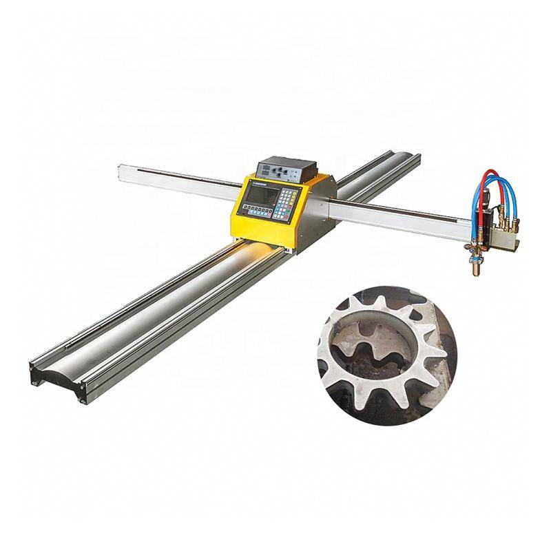
for Steel Structures, where plate flatness is rarely perfect, the AVC prevents torch collisions and ensures a uniform kerf width. Without this control, the arc would widen or narrow, leading to tapered edges and inconsistent part dimensions. In heavy structural applications, where heat-induced warping occurs during the cutting process, the AVC dynamically compensates for the rising or sinking of the material, preserving the programmed cut path accuracy.
Achieving Superior Intersection Accuracy
In the context of structural frameworks, Intersection Accuracy refers to the precision with which the plasma torch executes complex cutouts, bolt holes, and cope cuts where multiple members join. The geometry of a web-to-flange intersection on an H-beam requires the plasma arc to transition through varying thicknesses and angles without losing its directional stability.
Advanced CNC controllers now utilize kerf compensation algorithms that work in tandem with the plasma power supply. When the torch approaches a corner or an intersection, the feed rate is automatically adjusted to prevent over-burning, which is a common failure point in thicker sections. By maintaining a constant plasma gas pressure and synchronized torch movement, the system ensures that the “land” or the remaining material at the intersection meets the strict tolerances required for structural bolting and assembly.
H-Beam Processing and Structural Versatility
Processing H-beams presents unique challenges compared to flat plate cutting. The transition from the flange to the web involves a change in material density and structural orientation. Plasma machines designed for structural steel often utilize a multi-axis robotic head or a specialized rotatable gantry to reach all faces of the beam in a single pass.
H-beam processing with plasma technology eliminates the need for manual layout and drilling. The machine can execute complex copes, notches, and holes across the three faces of the beam simultaneously. The integration of AVC is even more critical here, as the torch must maintain its height while navigating the radius where the flange meets the web. This capability significantly reduces the material handling time, as the beam does not need to be flipped or repositioned for different operations.
Multi-Axis Beveling for Weld Preparation
Weld preparation is a significant bottleneck in structural steel fabrication. Traditional methods involve manual grinding or mechanical milling to create the necessary edge profiles. Plasma systems equipped with a 3D bevel head can produce V, Y, X, and K-cuts directly during the primary cutting phase. This integration of Beveling Capabilities into the plasma cycle reduces secondary processing time by up to 70%.
The challenge with beveling is the increased travel distance the arc must cover compared to a vertical cut. The AVC must be sophisticated enough to calculate the “effective” voltage based on the angle of the torch. For instance, a 45-degree bevel through a 20mm plate results in a travel path of approximately 28mm. The plasma controller must adjust the gas flow and current intensity to ensure the arc penetrates the entire depth while leaving a clean, slag-free surface ready for assembly.
Operational Reliability and Low Maintenance Requirements
In heavy industrial environments, dust, moisture, and high temperatures are constant threats to machinery. Plasma cutting systems are engineered for high-duty cycles with minimal intervention. The “low maintenance” profile of modern plasma systems stems from the simplification of the torch head and the longevity of consumables. High-definition systems now feature “quick-change” torch designs that allow operators to replace electrodes and nozzles in under a minute, minimizing downtime during high-volume production runs.
Furthermore, the absence of sensitive optical components makes plasma machines resilient to the vibrations and airborne particulates found in steel mills and fabrication shops. The primary maintenance requirements are centered on the filtration of the compressed air or gas supply and the periodic cleaning of the rack-and-pinion drive systems. Compared to other high-energy cutting methods, the cost-per-foot of plasma cutting remains the most competitive for structural steel thicknesses ranging from 10mm to 50mm.
Optimizing Throughput with Automated Nesting
To maximize the efficiency of the plasma machine, industrial engineers utilize automated nesting software. This software optimizes the layout of parts on the steel plate or beam to minimize scrap. When combined with a high-speed plasma arc, nesting allows for “bridge cutting” or “common line cutting,” where the torch moves continuously from one part to the next without extinguishing the arc. This reduces the number of pierces, which is the most wear-intensive part of the plasma process for the electrode. By reducing pierce cycles, the AVC and the torch assembly can operate for longer durations between consumable changes, further lowering the operational cost.
Summary of Engineering Advantages
The implementation of a Plasma Cutting Machine with Arc Voltage Control provides a measurable increase in fabrication accuracy and a decrease in lead times. For structural steel applications, the ability to handle complex intersections and provide ready-to-weld bevels on H-beams is indispensable. By focusing on the mechanical robustness of the gantry and the precision of the voltage feedback loop, fabrication facilities can achieve a high level of repeatability that is essential for the safety and integrity of modern steel structures.
In conclusion, the plasma process remains the backbone of the structural steel industry due to its versatility and ruggedness. As AVC technology continues to evolve, the gap between thermal cutting and mechanical machining continues to close, allowing for more ambitious architectural and engineering designs to be realized with greater efficiency and lower total cost of ownership.
-


LT240S tube laser cutting machine
-
LT120S tube laser cutting machine
-
Sale

Tank Fillet Welding Machine
Original price was: $1,000.00.$900.00Current price is: $900.00. -
Sale

MAK100 tube laser cutting machine
Original price was: $5,500.00.$5,000.00Current price is: $5,000.00. -

portable plasma air cutting machine
$1,200.00 -

2in1 fiber laser cutting machine
-

Air cooling Laser welding machine
-

HF h beam laser cutting machine
-

LT240 laser cutting machine
-

Laser welding machine
-


Cobot Welding Station
-

Gantry welding robot solution
-

Tracked Wheeled AGV Welding robot
-

LFH6020 Fiber laser cutting machine
-
LFP6020
-

robotic welidng machine
Advanced Fiber Laser Tube Processing Technology
Our CNC Fiber Laser Tube Cutting systems revolutionize metal fabrication by integrating high-precision cutting, punching, and profiling into a single automated workflow. Designed for versatility, this technology handles a wide array of profiles including Round, Square, Rectangular, and Oval tubes, as well as complex L-shaped and U-shaped channels.
- Precision Punching: High-speed hole punching with micron-level accuracy, eliminating the need for mechanical drilling or die-stamping.
- Complex Profiling: Advanced 3D pathing allows for intricate interlocking joints and specialized notch cuts, ideal for structural frames.
- High Material Efficiency: Intelligent nesting software minimizes scrap, reducing raw material costs across large production runs.
- Clean Finish: Delivers oxide-free, burr-free edges that require zero secondary grinding before welding.

Seamlessly processing multiple profiles with consistent precision.
Global Delivery & Logistics



From our high-tech manufacturing facility directly to your global site. PCL WeldCut ensures secure packaging, professional handling, and reliable international logistics to safeguard your equipment throughout the entire journey.