Optimizing Structural Steel Fabrication via Advanced Plasma Systems
In the realm of heavy structural engineering, the demand for high-throughput production cycles necessitates cutting technologies that balance speed with geometric precision. Plasma Cutting remains the primary solution for processing heavy-gauge H-beams, channels, and plates due to its ability to handle thick conductive materials with high thermal efficiency. Unlike mechanical sawing or punching, modern plasma systems integrated with multi-axis CNC controllers allow for complex geometries, including bolt holes, copes, and weld preparations, to be executed in a single handling cycle.
From an industrial engineering perspective, the efficiency of a plasma system is not merely defined by its cutting speed but by the stability of its arc and the accuracy of its motion control. For structural steel components like H-beams and I-sections, surface irregularities and material bowing are common. Without a mechanism to compensate for these fluctuations, the torch distance varies, leading to inconsistent kerf widths, excessive dross, and potential collision risks. This is where Arc Voltage Control (AVC) becomes a non-negotiable component of the system architecture.
The Mechanics of Arc Voltage Control in Z-Axis Stabilization
Arc voltage height control (THC) functions as a closed-loop feedback system. During the cutting process, the voltage between the plasma torch electrode and the workpiece is directly proportional to the distance of the arc gap. As the torch moves across a beam that may be slightly warped or out of level, the CNC system monitors the arc voltage in real-time. If the voltage increases, the system identifies that the torch-to-plate distance has widened and signals the Z-axis motor to lower the torch. Conversely, a drop in voltage triggers an immediate retraction.
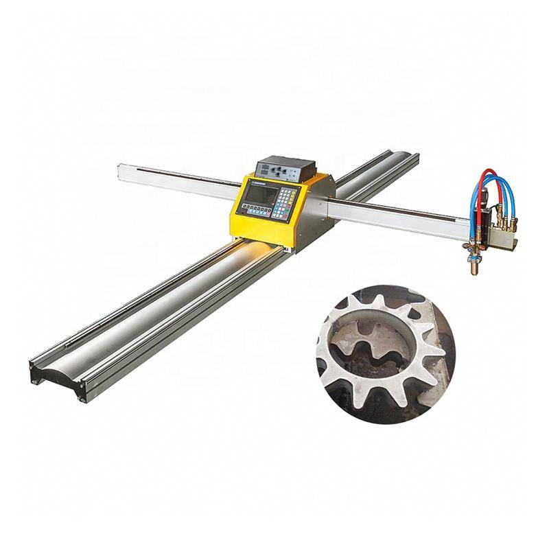
This dynamic adjustment is critical for structural steel because even a 1mm deviation in height can result in a change in the arc’s angularity and width. For high-definition plasma processes, maintaining a precise standoff distance ensures that the energy density remains concentrated at the focal point of the plasma stream. This results in cleaner edges and reduces the secondary labor costs associated with grinding and slag removal. Furthermore, the AVC system incorporates “Ohmic sensing” for initial height sensing (IHS), which allows the torch to locate the material surface accurately before every pierce, protecting the consumables from premature wear.
Precision Intersection Accuracy for Complex Structural Joints
Structural integrity in steel frameworks relies heavily on the fit-up of intersecting members. Whether it is a circular hollow section (CHS) intersecting an H-beam or a complex gusset plate connection, structural steel fabrication requires tight tolerances to ensure load distribution is consistent with the architectural design. Plasma systems equipped with 5-axis or 6-axis robotic heads utilize advanced algorithms to calculate the intersection path between two 3D objects.
Intersection accuracy is achieved through the synchronization of the plasma power source with the motion controller. When the torch navigates a tight radius or a complex bevel corner, the feed rate must be adjusted to prevent over-burning or rounding of the edges. Modern CNC controllers utilize “Look-Ahead” logic to decelerate the torch at corners and intersections while simultaneously modulating the plasma amperage. This prevents the “puddling” effect that often occurs when heat builds up in a specific area, ensuring that bolt holes are perfectly circular and that copes align precisely with the mating flange of an H-beam.
H-Beam Processing and Low Maintenance Design
The environment of a structural steel shop is characterized by heavy dust, metallic particles, and vibration. Traditional equipment often suffers from downtime due to the ingress of contaminants into linear guides and drive systems. High-performance plasma machines designed for H-beams prioritize a low-maintenance physical architecture. This includes the use of pressurized bellows for rail protection, hardened helical rack-and-pinion drives, and heavy-duty filtration systems for the plasma power supply.
Specifically, for H-beam lines, the “low maintenance” aspect is achieved through the integration of automated tool-path generation that minimizes torch travel and idle time. Since plasma systems do not require the sensitive optical alignments found in other thermal cutting methods, they are far more resilient to the physical shocks common when loading 12-meter beams onto a conveyor system. The consumables—nozzles, electrodes, and swirl rings—are the only primary wear items, and modern “quick-change” torch designs allow operators to swap these components in under 60 seconds, maintaining high OEE (Overall Equipment Effectiveness) ratings.
Beveling for Weld Preparation: V, X, and K Cuts
One of the most significant advantages of multi-axis bevel cutting is the elimination of secondary machining processes. For heavy structural plates and beam webs, a straight 90-degree cut is often insufficient; weld preparation requires specific bevel angles to ensure deep penetration during the assembly phase. Plasma systems with tilt-and-rotate heads can produce V-bevels, Y-bevels, and even complex K-bevels in a single pass.
The challenge in beveling is that the effective thickness of the material increases as the angle becomes more acute. For instance, cutting a 20mm plate at a 45-degree angle increases the travel distance through the metal to approximately 28mm. The AVC system must compensate for this change in resistance and voltage to keep the bevel angle consistent across the entire length of the cut. By integrating the bevel angle data into the CNC nesting software, the machine automatically adjusts the plasma gas mix and amperage to compensate for the increased material thickness, resulting in a surface finish that meets AWS (American Welding Society) standards without further refinement.
Data Integration and SEO Optimization of the Production Workflow
From a workflow management perspective, the plasma cutting station acts as the “gateway” for the entire fabrication shop. Files are typically exported from BIM (Building Information Modeling) software in DSTV or STEP formats and imported directly into the machine’s nesting software. This digital continuity ensures that the physical part matches the engineering model perfectly.
By implementing a plasma system with robust AVC and multi-axis capabilities, facilities can reduce the “cost per part” by minimizing scrap and maximizing material utilization. The ability to nest various parts across a single H-beam or plate, while maintaining high intersection accuracy, allows for leaner inventory management. Industrial engineers can track metrics such as “arc-on time” and “pierce counts” to further refine the maintenance schedules, ensuring that the machine operates within its peak efficiency envelope.
Technical Conclusion for Structural Integration
In summary, the application of plasma cutting technology in the structural steel sector is defined by its ruggedness and adaptability. The synergy between Arc Voltage Control and multi-axis motion control provides the precision required for complex intersections and beveling while maintaining the low-maintenance profile necessary for harsh industrial environments. By focusing on these core technical competencies—Z-axis stability, geometric accuracy, and robust mechanical design—manufacturers can significantly enhance their production capacity and structural quality.
-


LT240S tube laser cutting machine
-
LT120S tube laser cutting machine
-
Sale

Tank Fillet Welding Machine
Original price was: $1,000.00.$900.00Current price is: $900.00. -
Sale

MAK100 tube laser cutting machine
Original price was: $5,500.00.$5,000.00Current price is: $5,000.00. -

portable plasma air cutting machine
$1,200.00 -

2in1 fiber laser cutting machine
-

Air cooling Laser welding machine
-

HF h beam laser cutting machine
-

LT240 laser cutting machine
-

Laser welding machine
-


Cobot Welding Station
-

Gantry welding robot solution
-

Tracked Wheeled AGV Welding robot
-

LFH6020 Fiber laser cutting machine
-
LFP6020
-

robotic welidng machine
Advanced Fiber Laser Tube Processing Technology
Our CNC Fiber Laser Tube Cutting systems revolutionize metal fabrication by integrating high-precision cutting, punching, and profiling into a single automated workflow. Designed for versatility, this technology handles a wide array of profiles including Round, Square, Rectangular, and Oval tubes, as well as complex L-shaped and U-shaped channels.
- Precision Punching: High-speed hole punching with micron-level accuracy, eliminating the need for mechanical drilling or die-stamping.
- Complex Profiling: Advanced 3D pathing allows for intricate interlocking joints and specialized notch cuts, ideal for structural frames.
- High Material Efficiency: Intelligent nesting software minimizes scrap, reducing raw material costs across large production runs.
- Clean Finish: Delivers oxide-free, burr-free edges that require zero secondary grinding before welding.

Seamlessly processing multiple profiles with consistent precision.
Global Delivery & Logistics



From our high-tech manufacturing facility directly to your global site. PCL WeldCut ensures secure packaging, professional handling, and reliable international logistics to safeguard your equipment throughout the entire journey.