Optimizing Pressure Vessel Fabrication with Plasma Cutting Systems
In the heavy industrial sector, the fabrication of pressure vessels requires rigorous adherence to geometric tolerances and structural integrity. A specialized Plasma Cutting Machine equipped with advanced sensor feedback is no longer an optional upgrade but a fundamental requirement for facilities aiming to meet ASME or ISO standards. Industrial engineers must prioritize systems that stabilize the cutting environment, particularly when dealing with large-scale cylindrical shells and dished ends where surface irregularities are common.
The Engineering Logic of Arc Voltage Control (AVC)
The core of modern plasma efficiency lies in the arc voltage control system. In pressure vessel manufacturing, material surfaces are rarely perfectly flat or concentric. Thermal expansion during the cutting process and inherent mill tolerances in heavy plates create height variances that can jeopardize cut quality. AVC functions as a closed-loop feedback system that measures the voltage between the electrode and the workpiece.
As the distance between the plasma torch and the plate changes, the arc voltage fluctuates proportionally. The AVC system detects these micro-variations and triggers the Z-axis motor to adjust the torch height in real-time. This maintains a constant standoff distance, which is critical for preserving the kerf width and preventing dross accumulation. For an industrial engineer, this translates to reduced secondary grinding operations and a significant decrease in torch consumable wear, as pilot arc crashes are virtually eliminated.
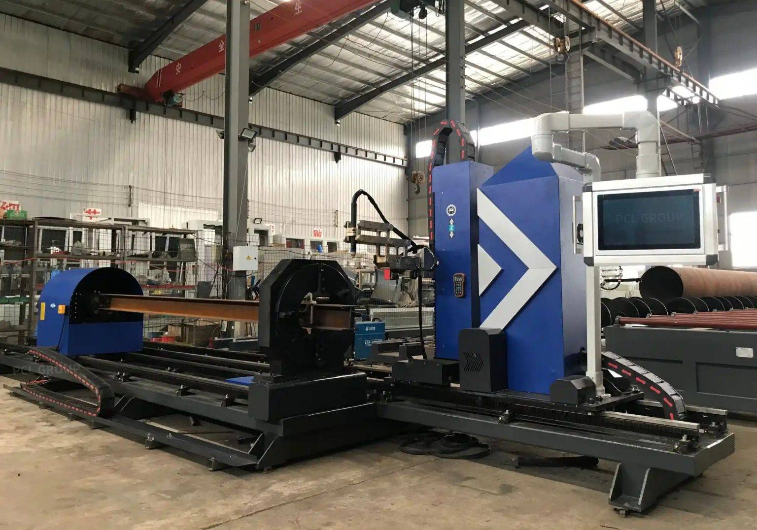
Precision in Intersection Accuracy for Nozzle Penetrations
One of the most complex tasks in vessel fabrication is the creation of holes for nozzles, manways, and instrumentation ports. These cuts often occur on a curved surface, requiring the plasma head to follow a non-linear path that accounts for the vessel’s radius. Achieving high intersection accuracy is vital for ensuring that the fit-up between the shell and the nozzle neck is airtight and structurally sound.
Advanced plasma systems utilize 5-axis or 6-axis kinematic movements to maintain the torch’s perpendicularity or specific bevel angle relative to the curved surface tangent. When the intersection is calculated correctly by the CNC software, the resulting hole allows for a seamless “set-in” or “set-on” nozzle configuration. High intersection accuracy minimizes the “root gap” variability, which is essential for automated welding processes that follow the cutting stage. By eliminating manual layout and hand-cutting, the facility reduces human error and accelerates the production cycle of the shell assembly.
H-Beam Structural Design and Low Maintenance Requirements
The structural rigidity of the cutting machine’s gantry and bed determines its long-term reliability. In a heavy-duty industrial environment, lightweight aluminum extrusions often fail to provide the necessary dampening for high-speed plasma vibrations. Utilizing an H-beam construction for the gantry and longitudinal rails offers superior moment of inertia and torsional stiffness.
From a maintenance perspective, H-beam based systems are designed for high-duty cycles. The mass of the H-beam minimizes harmonic resonance, which protects the precision gear racks and linear guides from premature wear. For the industrial engineer, this results in a low maintenance profile. Hardened ground rails mounted on machined H-beam surfaces ensure that the machine maintains its calibration over years of three-shift operations. Furthermore, the open design of these heavy-duty frames allows for easier slag removal and less buildup of metallic dust, further extending the service life of the mechanical drive components.
Multi-Axis Beveling for Weld Preparation
Pressure vessels are typically constructed from thick carbon steel or stainless steel plates, requiring specific edge geometries (V, Y, X, or K-cuts) for full-penetration welds. A plasma system with a rotatable bevel head allows these profiles to be cut in a single pass. This eliminates the need for a separate edge-milling process or manual oxy-fuel beveling.
The integration of AVC is particularly crucial during beveling. Because the torch is tilted, the relationship between arc voltage and physical distance changes. Sophisticated CNC controllers compensate for this by adjusting the voltage setpoints based on the bevel angle. This ensures that the “land” of the weld prep remains consistent throughout the entire circumference of a shell or the perimeter of a dished head. Consistency in the bevel land is the primary factor in achieving high-quality sub-arc or MIG welds in subsequent assembly stages.
Thermal Distortion Mitigation and Material Utilization
Industrial engineers must also account for the thermal input of the plasma arc. Large pressure vessel fabrication projects involve significant material costs. Plasma cutting, when synchronized with water tables or high-volume downdraft systems, helps in managing the Heat Affected Zone (HAZ). By optimizing the cutting sequence and using the precision afforded by AVC, engineers can nest parts more tightly, improving material utilization rates.
The speed of plasma cutting—often three to five times faster than oxy-fuel on medium thicknesses—reduces the total heat energy absorbed by the plate. This limits the “bowing” or “warping” of the shell plates, ensuring that when the plates are rolled, the edges meet with minimal mechanical forcing. This precision at the component level ripples through the entire assembly process, reducing the need for rework and heavy-duty clamping.
Workflow Integration and Digital Documentation
Modern plasma systems provide data outputs that are invaluable for quality control departments. Every cut can be logged with its associated parameters, including arc voltage, feed rate, and gas pressures. This digital trail supports the traceability requirements often found in the oil, gas, and nuclear power industries. When a machine maintains high intersection accuracy and consistent bevel profiles, the facility can move toward a “just-in-time” assembly model, where components move directly from the cutting table to the rolling and welding stations without intermediate buffer stages for correction.
Conclusion for the Industrial Engineer
Selecting a plasma cutting system for pressure vessel work requires a focus on structural stability and reactive height control. By prioritizing H-beam construction for durability and AVC for precision, manufacturers can overcome the challenges of curved-surface geometry and thick-plate weld preparation. The result is a streamlined production line characterized by high throughput, minimal manual intervention, and superior geometric accuracy in nozzle intersections.
-


Cantilever Welding Robot solution
-


GF laser cutting machine
-

P3015 plasma cutting machine
-

LFP3015 Fiber Laser Cutter
-

pipe plasma cutting machine
-
LFH 4020 Fiber Laser Cutting Machine
-
LFP4020
-

gantry plasma air cutting machine
-

3D robot cutting machine
-

8 axis plasma cutting machine
-

5 axis plasma cutting machine
-

LT360 tube laser cutting machine
-

robot welding workstation
-

SF6060 fiber laser cutting machine
Advanced Fiber Laser Tube Processing Technology
Our CNC Fiber Laser Tube Cutting systems revolutionize metal fabrication by integrating high-precision cutting, punching, and profiling into a single automated workflow. Designed for versatility, this technology handles a wide array of profiles including Round, Square, Rectangular, and Oval tubes, as well as complex L-shaped and U-shaped channels.
- Precision Punching: High-speed hole punching with micron-level accuracy, eliminating the need for mechanical drilling or die-stamping.
- Complex Profiling: Advanced 3D pathing allows for intricate interlocking joints and specialized notch cuts, ideal for structural frames.
- High Material Efficiency: Intelligent nesting software minimizes scrap, reducing raw material costs across large production runs.
- Clean Finish: Delivers oxide-free, burr-free edges that require zero secondary grinding before welding.

Seamlessly processing multiple profiles with consistent precision.
Global Delivery & Logistics



From our high-tech manufacturing facility directly to your global site. PCL WeldCut ensures secure packaging, professional handling, and reliable international logistics to safeguard your equipment throughout the entire journey.