Optimizing Pressure Vessel Fabrication with Arc Voltage Control
In the field of heavy industrial manufacturing, specifically the production of pressure vessels and heat exchangers, the precision of primary cuts determines the efficiency of the entire assembly line. The integration of Plasma Cutting Machine with Arc Voltage Control (AVC) technology has shifted the paradigm from manual layout and grinding to high-velocity, automated precision. For industrial engineers, the objective is to minimize material waste while ensuring that shell-to-nozzle intersections meet stringent ASME or ISO standards. Plasma systems, unlike mechanical shearing, offer the thermal energy required to penetrate thick-walled carbon steel and stainless steel alloys common in the oil, gas, and nuclear sectors.
The Technical Necessity of Arc Voltage Control (AVC)
In plasma cutting, the distance between the torch tip and the workpiece—the standoff distance—is the most critical variable affecting cut quality and kerf width. Pressure vessels often present non-linear surfaces; shells may have slight ovality or surface irregularities from the rolling process. Without automated adjustment, a fixed-height torch would either collide with the plate or move too far away, causing the arc to extinguish or “lag,” resulting in excessive dross and poor edge angularity.
Arc Voltage Control functions as a real-time feedback loop. The system monitors the voltage of the plasma arc, which is directly proportional to the distance between the electrode and the metal. If the voltage fluctuates, the CNC Z-axis motor makes instantaneous micro-adjustments to maintain a constant gap. For pressure vessel manufacturers, this means consistent penetration and uniform heat-affected zones (HAZ) across the entire circumference of a cylinder or the curvature of a dished head.
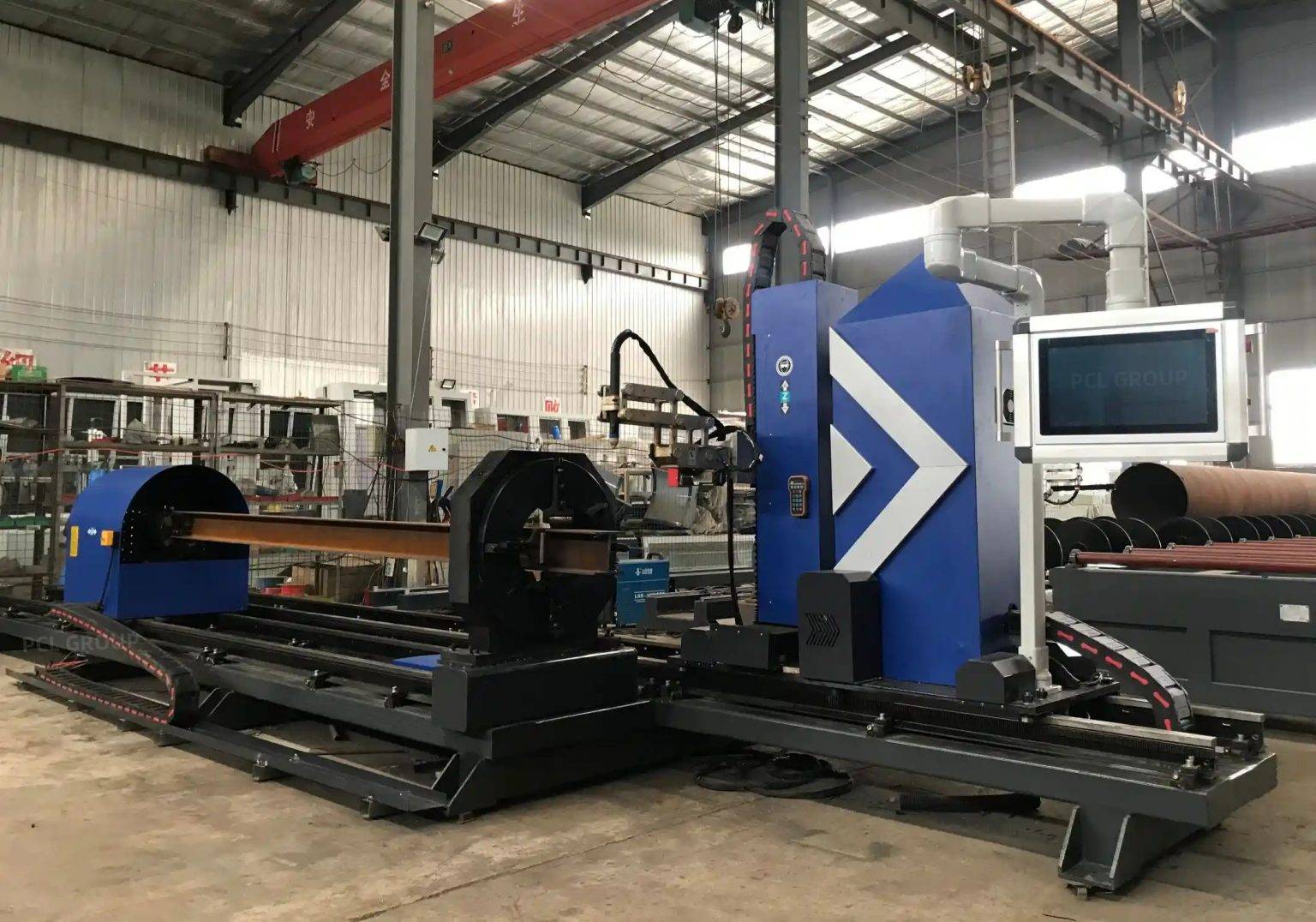
Intersection Accuracy in Nozzle and Shell Integration
The most complex geometric challenge in vessel fabrication is the “saddle cut” or the intersection where a nozzle meets the main shell. These 3D geometries require the plasma head to move through multi-axis paths while maintaining a consistent distance from a curved surface. High-definition plasma systems, when paired with sophisticated 5-axis motion controllers, achieve intersection accuracy that eliminates the need for manual refitting.
By utilizing mathematical algorithms that calculate the intersection of two cylinders, the plasma machine can execute a compensated path. This path accounts for the wall thickness of both the shell and the nozzle, ensuring that the root gap is consistent for subsequent welding operations. High intersection accuracy translates directly to a reduction in “fill time” during welding. When the fit-up is tight and the tolerances are held within +/- 0.5mm, the volume of weld metal required is minimized, significantly lowering the cost of consumables and labor.
H-Beam Structural Integrity and Low Maintenance
From an industrial maintenance perspective, the chassis of the plasma cutting system is as vital as the electronics. Heavy-duty plasma machines for pressure vessel components often utilize a H-beam low maintenance structure for the gantry and the rails. Unlike lighter aluminum extrusions, the high-mass H-beam design provides superior vibration damping. In an environment where heavy plates are loaded via overhead cranes, the robustness of the H-beam ensures the machine retains its calibration over years of three-shift operations.
The choice of an H-beam foundation reduces the frequency of mechanical leveling and rail alignment. In a high-dust environment—typical of metal fabrication—the linear guide systems mounted on rigid H-beams are easier to protect and clean. For the facility manager, this results in a lower Total Cost of Ownership (TCO). The rigidity of the H-beam also supports higher acceleration and deceleration rates of the gantry, which is essential when cutting complex small-diameter holes for instrument nozzles where rapid direction changes are required.
Advanced Beveling for Weld Preparation
The final stage of preparation for Pressure Vessels is the creation of weld bevels. Standard straight cuts are rarely sufficient; thick-walled vessels require V, Y, X, or K-type bevels to allow for full-depth weld penetration. Modern plasma systems feature beveling heads that can tilt up to 45 or 50 degrees. Integrated with AVC, these heads can perform “on-the-fly” beveling where the angle changes dynamically as the torch moves around a circular cutout.
This automated beveling capability is a significant force multiplier. Traditionally, a worker would have to use a hand-held oxy-fuel torch or a mechanical beveler after the initial hole was cut. By performing the beveling during the primary plasma cutting cycle, the part is ready for the assembly floor immediately upon leaving the cutting table. The precision of a plasma-cut bevel ensures that the land thickness is uniform, which is a prerequisite for automated submerged arc welding (SAW) processes used in vessel longitudinal and circumferential seams.
Thermal Management and Material Efficiency
Industrial engineers must also consider the thermal dynamics of plasma cutting. High-definition plasma (HDP) focuses the arc through a smaller orifice, increasing the energy density. This results in a narrower kerf and less heat input into the base material. When cutting high-strength steels used in pressure vessels, minimizing the HAZ is critical to maintaining the mechanical properties of the alloy. The speed of the plasma process, often three to five times faster than oxy-fuel on medium thicknesses, ensures that the bulk temperature of the part remains low, preventing thermal distortion that could interfere with the vessel’s final roundness.
Operational Synergy: Software and Hardware
The effectiveness of the AVC and the H-beam structure is unlocked by the Nesting Software. For pressure vessel production, nesting must account for the specific grain direction of the plate and the exact dimensions of the rolled shells. The software communicates directly with the CNC to adjust the plasma gas flow and current based on the material thickness and the required bevel angle. This “smart” integration ensures that the first cut is as accurate as the last, regardless of operator experience level.
Furthermore, the data collected by the AVC system can be used for predictive maintenance. Fluctuations in the voltage baseline often signal that the electrode or nozzle is reaching the end of its life. By replacing consumables before they fail, manufacturers avoid “mid-cut” failures that can scrap expensive large-format plates. This proactive approach to consumable management is a hallmark of a lean manufacturing facility.
Conclusion
For the industrial engineer, the implementation of a Plasma Cutting Machine with Arc Voltage Control represents a strategic investment in both quality and throughput. By prioritizing a heavy-duty H-beam construction, the facility ensures long-term geometric stability and minimal downtime. The ability to achieve high intersection accuracy on complex 3D profiles and automate the beveling process directly addresses the most labor-intensive aspects of pressure vessel fabrication. In an industry where safety and structural integrity are non-negotiable, the precision offered by modern plasma technology provides the necessary foundation for excellence in heavy-duty manufacturing.
-


Cantilever Welding Robot solution
-


GF laser cutting machine
-

P3015 plasma cutting machine
-

LFP3015 Fiber Laser Cutter
-

pipe plasma cutting machine
-
LFH 4020 Fiber Laser Cutting Machine
-
LFP4020
-

gantry plasma air cutting machine
-

3D robot cutting machine
-

8 axis plasma cutting machine
-

5 axis plasma cutting machine
-

LT360 tube laser cutting machine
-

robot welding workstation
-

SF6060 fiber laser cutting machine
Advanced Fiber Laser Tube Processing Technology
Our CNC Fiber Laser Tube Cutting systems revolutionize metal fabrication by integrating high-precision cutting, punching, and profiling into a single automated workflow. Designed for versatility, this technology handles a wide array of profiles including Round, Square, Rectangular, and Oval tubes, as well as complex L-shaped and U-shaped channels.
- Precision Punching: High-speed hole punching with micron-level accuracy, eliminating the need for mechanical drilling or die-stamping.
- Complex Profiling: Advanced 3D pathing allows for intricate interlocking joints and specialized notch cuts, ideal for structural frames.
- High Material Efficiency: Intelligent nesting software minimizes scrap, reducing raw material costs across large production runs.
- Clean Finish: Delivers oxide-free, burr-free edges that require zero secondary grinding before welding.

Seamlessly processing multiple profiles with consistent precision.
Global Delivery & Logistics



From our high-tech manufacturing facility directly to your global site. PCL WeldCut ensures secure packaging, professional handling, and reliable international logistics to safeguard your equipment throughout the entire journey.