Optimizing Oil and Gas Tank Fabrication via Advanced Plasma Systems
The engineering requirements for oil and gas storage tanks demand rigorous adherence to geometric tolerances and structural integrity. As these vessels often hold volatile or hazardous materials, the initial fabrication phase—specifically the cutting and shaping of carbon steel and stainless steel plates—sets the foundation for the entire project. Utilizing a Plasma Cutting Machine equipped with high-definition power sources and sophisticated control systems is no longer an option but a necessity for facilities aiming for high throughput and precision.
The Critical Role of Arc Voltage Control (AVC)
In the context of large-scale tank fabrication, material flatness is rarely perfect. Large-format plates used for tank shells or bottoms often exhibit undulations, bowing, or internal stresses that cause the material to shift during the thermal cutting process. This is where Arc Voltage Control (AVC) becomes the primary driver of quality. AVC operates on the principle that the voltage of the plasma arc is directly proportional to the distance between the torch tip and the workpiece.
By continuously monitoring the arc voltage at millisecond intervals, the CNC system can command the Z-axis lifter to maintain a constant standoff height. This real-time adjustment is vital for Arc Voltage Control because even a millimeter of deviation in torch height can result in kerf width variations, increased dross accumulation, and angular deviations. For oil and gas tanks, where shell plates must be perfectly cylindrical when rolled, any inconsistency in the cut edge can lead to fit-up issues during assembly, necessitating costly field corrections.
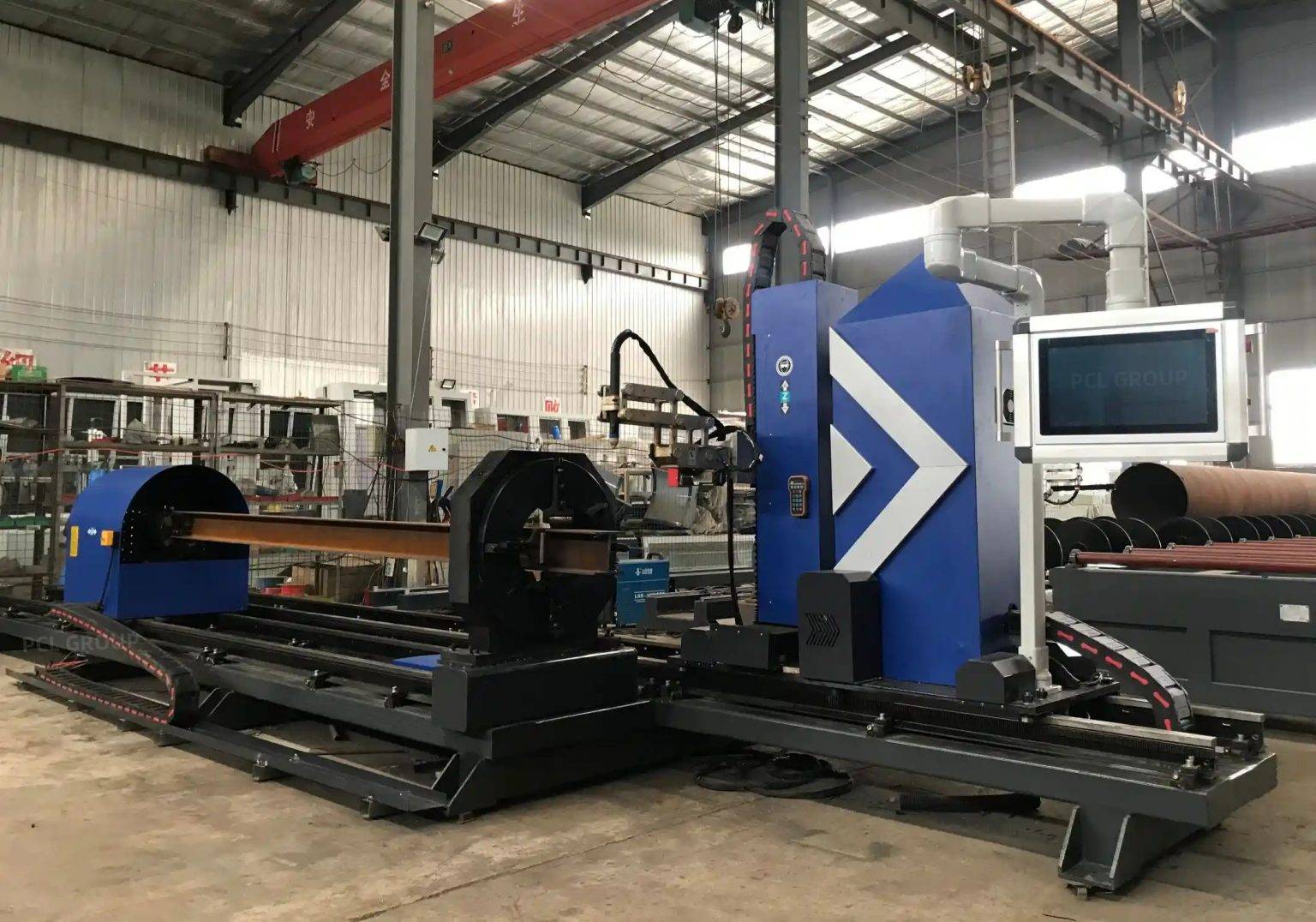
Achieving Superior Intersection Accuracy
Oil and gas tanks are complex assemblies featuring numerous nozzle penetrations, manways, and structural attachments. The Intersection Accuracy required for these apertures is exceptionally high. When a circular nozzle intersects a cylindrical tank shell at an angle, the resulting cutout is a complex 3D saddle curve. A high-precision plasma system must calculate these paths with extreme fidelity to ensure that the nozzle fits the aperture with a uniform gap for subsequent welding processes.
The integration of advanced nesting software and precision motion controllers allows the plasma torch to follow these non-linear paths without decelerating excessively, which would otherwise cause “over-burn” at corners or tight radii. By maintaining a constant feed rate and utilizing the AVC to navigate the curvature of the shell, the machine ensures that the intersection points are surgically precise. This reduces the need for manual trimming and ensures that the structural integrity of the reinforcement pads and nozzles remains intact according to engineering specifications.
H-Beam Gantry Design and Low Maintenance Requirements
From a mechanical engineering perspective, the bridge or gantry of the plasma machine is the backbone of the system. In heavy industrial environments like tank farms or shipyards, lightweight aluminum gantries often fail to provide the necessary vibration damping and thermal stability. The implementation of heavy-duty H-beam construction for the gantry and longitudinal rails offers a significant advantage in terms of low maintenance and longevity.
The H-beam structure provides a high moment of inertia, resisting the torsional forces generated during high-speed directional changes of the plasma head. This rigidity prevents “ringing” or oscillations that can manifest as wavy cut edges. Furthermore, the mass of the H-beam serves as a heat sink, minimizing the thermal expansion that can occur in high-temperature fabrication shops. For the maintenance engineer, this translates to fewer recalibration cycles, reduced wear on drive motors and gearboxes, and a significantly longer service life for the linear bearings and rack-and-pinion systems.
Precision Beveling for Weld Preparation
Perhaps the most significant bottleneck in tank fabrication is the preparation of plate edges for welding. Heavy-wall tanks require specific edge geometries—V-grooves, Y-grooves, or X-grooves—to ensure full penetration welds. Traditional manual beveling is labor-intensive and prone to human error. Modern Beveling Operations integrated into plasma systems allow for the automated creation of these profiles in a single pass.
The plasma bevel head, often featuring a 5-axis configuration with infinite rotation, can tilt the torch to the required angle while the AVC maintains the precise focal point of the arc. This capability is crucial when cutting the edges of thick plates that will form the vertical or girth seams of the tank. By producing a clean, oxide-free bevel with consistent land thickness, the plasma machine eliminates the need for secondary grinding. This not only speeds up the fabrication cycle but also ensures that the weld volume remains consistent, leading to more predictable weld quality and reduced filler metal consumption.
Enhancing Operational Efficiency through CNC Integration
The synergy between the CNC controller and the plasma power source allows for the automation of gas pressures and flow rates based on the material thickness and type. When cutting the 304 or 316L stainless steel often required for internal tank liners or specialized chemical storage, the system can automatically switch to Nitrogen or H35 (Hydrogen/Argon mix) to prevent oxidation. This level of control, combined with the mechanical stability of the H-beam frame, ensures that the machine remains productive for multiple shifts with minimal intervention.
Thermal Management and Material Stability
Large-scale plasma cutting generates significant localized heat. In tank fabrication, managing this heat is essential to prevent plate warping. The high travel speeds of modern plasma systems, often exceeding 300 inches per minute on thinner gauges, minimize the Heat Affected Zone (HAZ). By combining high-speed motion with the precision of AVC, the energy input is concentrated exactly where needed, preserving the metallurgical properties of the parent metal, which is critical for pressure-retaining components in the oil and gas sector.
Conclusion: The Industrial Engineering Advantage
The deployment of a high-performance plasma system for oil and gas tank fabrication represents a strategic investment in quality and efficiency. By focusing on the mechanical rigidity of H-beam designs, the real-time adaptability of Arc Voltage Control, and the geometric precision of 5-axis beveling, manufacturers can achieve a level of intersection accuracy that was previously unattainable. These technical advancements collectively drive down the total cost of ownership by reducing manual labor, minimizing material waste, and ensuring that every component meets the stringent safety standards of the energy industry.
-


LT240S tube laser cutting machine
-
LT120S tube laser cutting machine
-
Sale

Tank Fillet Welding Machine
Original price was: $1,000.00.$900.00Current price is: $900.00. -
Sale

MAK100 tube laser cutting machine
Original price was: $5,500.00.$5,000.00Current price is: $5,000.00. -

portable plasma air cutting machine
$1,200.00 -

2in1 fiber laser cutting machine
-

Air cooling Laser welding machine
-

HF h beam laser cutting machine
-

LT240 laser cutting machine
-

Laser welding machine
-


Cobot Welding Station
-

Gantry welding robot solution
-

Tracked Wheeled AGV Welding robot
-

LFH6020 Fiber laser cutting machine
-
LFP6020
-

robotic welidng machine
Advanced Fiber Laser Tube Processing Technology
Our CNC Fiber Laser Tube Cutting systems revolutionize metal fabrication by integrating high-precision cutting, punching, and profiling into a single automated workflow. Designed for versatility, this technology handles a wide array of profiles including Round, Square, Rectangular, and Oval tubes, as well as complex L-shaped and U-shaped channels.
- Precision Punching: High-speed hole punching with micron-level accuracy, eliminating the need for mechanical drilling or die-stamping.
- Complex Profiling: Advanced 3D pathing allows for intricate interlocking joints and specialized notch cuts, ideal for structural frames.
- High Material Efficiency: Intelligent nesting software minimizes scrap, reducing raw material costs across large production runs.
- Clean Finish: Delivers oxide-free, burr-free edges that require zero secondary grinding before welding.

Seamlessly processing multiple profiles with consistent precision.
Global Delivery & Logistics



From our high-tech manufacturing facility directly to your global site. PCL WeldCut ensures secure packaging, professional handling, and reliable international logistics to safeguard your equipment throughout the entire journey.