Optimizing Pressure Vessel Fabrication via 5-Axis Plasma Technology
In the field of heavy industrial engineering, the fabrication of pressure vessels demands rigorous adherence to geometric tolerances and structural integrity standards, such as those defined by ASME Section VIII. Traditional methods of manual layout and mechanical cutting often lead to inconsistencies that complicate the assembly phase. The implementation of a 5-axis plasma beveling system represents a paradigm shift in how cylindrical shells and end caps are processed. By automating the intersection profiles and weld preparations, manufacturers can achieve a level of repeatability that manual processes cannot match.
Industrial engineers prioritize the reduction of “non-value-added” time. In pressure vessel production, this typically involves the secondary grinding and fit-up adjustments required when parts do not align perfectly. A CNC-driven plasma system addresses these inefficiencies at the source, ensuring that every cut is programmed with precise kerf compensation and thermal distortion modeling.
The Mechanics of 5-Axis Kinematics in Beveling
Standard 3-axis cutting systems are limited to vertical penetrations, which are insufficient for the complex weld geometries required in vessel construction. A 5-axis head introduces two rotational axes (typically A and B), allowing the plasma torch to tilt and rotate dynamically during the cut. This capability is essential for creating V, Y, X, and K-style bevels.
Geometric Versatility for Weld Prep
When preparing a heavy-wall shell for longitudinal or circumferential welding, the edge must be beveled to allow for full-penetration welds. The 5-axis system adjusts the torch angle in real-time, maintaining a constant bevel degree even as the torch travels along a curved surface. This precision ensures that the root gap remains uniform across the entire joint, which is a critical factor in preventing weld defects such as lack of fusion or inclusions.
Precision in Intersection Accuracy for Nozzles and Manways
One of the most complex challenges in pressure vessel fabrication is the creation of nozzle openings. These are rarely simple circular cuts; rather, they are complex intersections between two cylinders of different diameters. The resulting “saddle” shape requires varying bevel angles around the perimeter of the hole to ensure a flush fit for the nozzle pipe.
Mathematical Modeling of Saddle Cuts
The intersection accuracy provided by high-end plasma software calculates the exact coordinate path for the torch. As the torch moves around the diameter of the shell, the 5-axis head compensates for the changing surface curvature. This eliminates the need for manual “template and wrap” methods. For an industrial engineer, this precision translates directly into a reduced “heat-affected zone” (HAZ) and a much cleaner fit-up, which accelerates the subsequent welding stages.
Structural Foundation: The H-Beam Advantage
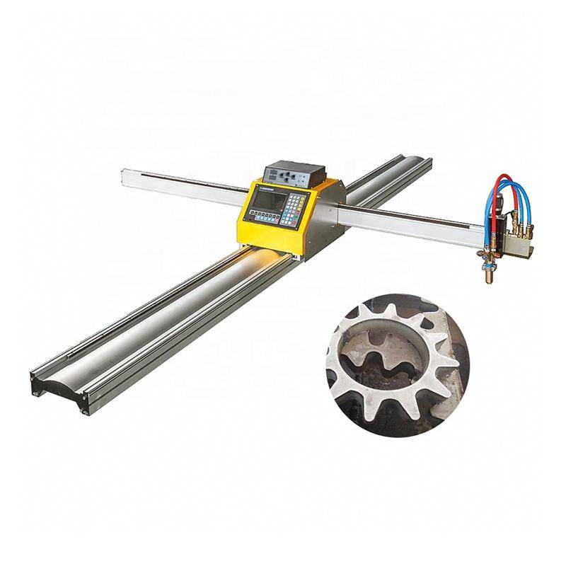
The longevity and accuracy of a Plasma Cutting Machine are heavily dependent on its structural frame. Heavy-duty 5-axis machines often utilize an H-beam gantry and bed design. Unlike lighter sheet-metal frames, the H-beam construction provides the torsional rigidity necessary to support the weight of heavy-walled vessels and the dynamic forces generated by high-speed torch movements.
Low Maintenance and Mechanical Reliability
From a maintenance perspective, the stability of an H-beam low maintenance design cannot be overstated. Vibration is the enemy of plasma arc stability. By utilizing a rigid, vibration-dampening frame, the machine preserves the alignment of its linear guides and rack-and-pinion drive systems. This reduces the frequency of recalibration and extends the service life of the mechanical components. In a high-throughput facility, minimizing downtime for machine adjustment is as vital as the cutting speed itself.
Furthermore, these industrial frames are designed to withstand the harsh environment of a fabrication shop, where dust, slag, and heat are constant. High-quality bellows and shielded drive systems ensure that the precision components remain isolated from debris, further contributing to the machine’s reliability.
Enhancing Process Efficiency Through CNC Integration
The transition from CAD design to physical cut is seamless in modern CNC plasma cutting environments. Industrial engineers can import 3D models of the entire pressure vessel into the CAM software. The software then nests the parts and calculates the optimal toolpaths, including lead-ins and lead-outs that minimize material waste.
Thermal Control and Dross Management
Advanced plasma power sources coupled with 5-axis control allow for precise modulation of gas flow and amperage. When performing a bevel cut, the material thickness effectively increases as the angle becomes more acute. The CNC system compensates by adjusting the cutting speed and arc voltage to maintain a consistent kerf width. This level of control results in “low-dross” cuts, significantly reducing the labor-intensive process of chipping away slag from the interior or exterior of the vessel components.
Quantifiable Benefits for Industrial Engineering Workflows
When evaluating the return on investment for 5-axis plasma equipment, the industrial engineer looks at several key performance indicators (KPIs):
- Reduction in total fabrication man-hours per vessel.
- Decrease in consumable costs through optimized nesting and arc-on time.
- Improved safety by reducing the need for manual torch operations and heavy grinding.
- Enhanced quality control with documented, repeatable cutting parameters.
By focusing on the core strengths of plasma technology—specifically its ability to handle thick carbon steel and stainless steel with high speed and efficiency—manufacturers can secure a competitive advantage in the global pressure vessel market. The 5-axis system is not merely a cutting tool; it is a critical component of a lean manufacturing strategy designed to eliminate bottlenecks in the preparation phase.
Conclusion: The Future of Vessel Preparation
As the demand for larger and more complex pressure vessels grows in sectors like oil and gas, chemical processing, and power generation, the reliance on automated plasma cutting will only increase. The synergy between 5-axis plasma beveling and robust mechanical design provides a foundation for high-quality production. By prioritizing intersection accuracy and selecting machines built on stable H-beam platforms, engineering firms ensure that their fabrication processes are both efficient and sustainable for long-term industrial operations.
-


LT240S tube laser cutting machine
-
LT120S tube laser cutting machine
-
Sale

Tank Fillet Welding Machine
Original price was: $1,000.00.$900.00Current price is: $900.00. -
Sale

MAK100 tube laser cutting machine
Original price was: $5,500.00.$5,000.00Current price is: $5,000.00. -

portable plasma air cutting machine
$1,200.00 -

2in1 fiber laser cutting machine
-

Air cooling Laser welding machine
-

HF h beam laser cutting machine
-

LT240 laser cutting machine
-

Laser welding machine
-


Cobot Welding Station
-

Gantry welding robot solution
-

Tracked Wheeled AGV Welding robot
-

LFH6020 Fiber laser cutting machine
-
LFP6020
-

robotic welidng machine
Advanced Fiber Laser Tube Processing Technology
Our CNC Fiber Laser Tube Cutting systems revolutionize metal fabrication by integrating high-precision cutting, punching, and profiling into a single automated workflow. Designed for versatility, this technology handles a wide array of profiles including Round, Square, Rectangular, and Oval tubes, as well as complex L-shaped and U-shaped channels.
- Precision Punching: High-speed hole punching with micron-level accuracy, eliminating the need for mechanical drilling or die-stamping.
- Complex Profiling: Advanced 3D pathing allows for intricate interlocking joints and specialized notch cuts, ideal for structural frames.
- High Material Efficiency: Intelligent nesting software minimizes scrap, reducing raw material costs across large production runs.
- Clean Finish: Delivers oxide-free, burr-free edges that require zero secondary grinding before welding.

Seamlessly processing multiple profiles with consistent precision.
Global Delivery & Logistics



From our high-tech manufacturing facility directly to your global site. PCL WeldCut ensures secure packaging, professional handling, and reliable international logistics to safeguard your equipment throughout the entire journey.