Advanced Plasma Cutting Integration for Construction Machinery
In the heavy equipment manufacturing sector, the demand for structural integrity and rapid assembly is paramount. Construction machinery, ranging from excavators to mobile cranes, relies on massive steel frameworks that must withstand high dynamic loads. The transition to plasma 5-axis beveling technology has redefined the efficiency of preparing these components. Unlike traditional 2D cutting, 5-axis plasma systems provide the necessary kinematic flexibility to handle complex geometries on thick plates and structural profiles.
Industrial engineers prioritize plasma systems for these applications due to their high duty cycles and ability to process mild steel in the 15mm to 50mm range with high velocity. The integration of a 5-axis head allows for the creation of weld-ready edges directly on the cutting table, removing the bottleneck of manual edge preparation. This synchronization of cutting and beveling into a single process flow is critical for maintaining lean manufacturing principles in high-volume production environments.
Kinematics of 5-Axis Beveling Heads
The core of a 5-axis plasma machine is its articulating head, which adds two rotational axes (typically A and B or C) to the standard X, Y, and Z Cartesian coordinates. For construction machinery fabrication, this allows the torch to tilt up to 45 or 50 degrees. This capability is essential for creating V, Y, X, and K-cross sections required for deep penetration welds in chassis and boom assemblies.
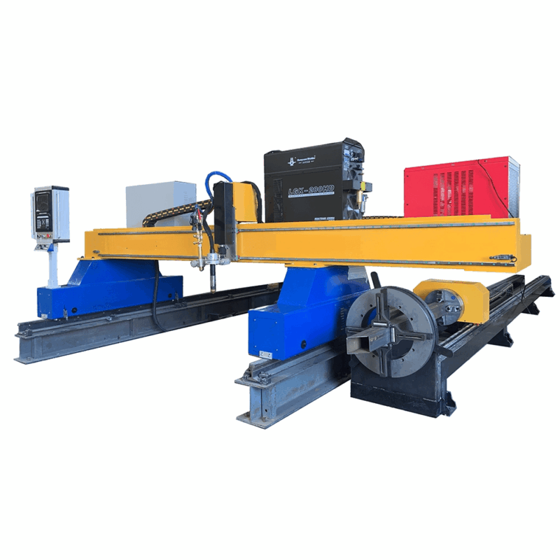
Precision in these systems is managed through sophisticated CNC algorithms that compensate for arc lead and kerf width variations at different angles. When the torch tilts, the effective thickness of the material increases, requiring the system to adjust gas pressure and current in real-time. High-definition plasma power sources are utilized to maintain a constricted, high-energy arc that ensures the intersection accuracy of complex parts remains within the tight tolerances required for robotic assembly.
H-Beam Processing and Structural Optimization
Structural steel, particularly H-beams and I-beams, forms the backbone of heavy lifting equipment. Standard 2D cutting is insufficient for the three-dimensional nature of these profiles. 5-axis plasma systems designed for beam processing utilize either a rotating gantry or a robotic arm to reach all faces of the beam. This allows for the cutting of bolt holes, web notches, and flange bevels in a single setup.
A significant advantage of plasma in this context is its H-beam low maintenance requirement. In the dusty and vibration-heavy environment of a structural steel shop, plasma torches are remarkably resilient. The consumables—nozzles, electrodes, and swirl rings—are designed for rapid replacement, and the absence of sensitive optical components means the system can operate at peak performance with minimal downtime. For an industrial engineer, this translates to a lower Total Cost of Ownership (TCO) and higher machine availability compared to more delicate cutting technologies.
Achieving High Intersection Accuracy
The accuracy of intersections in 3D space is the primary metric for evaluating a 5-axis plasma system. In the assembly of crane booms, where multiple plates converge at varying angles, the fit-up must be nearly perfect to ensure structural safety. Intersection accuracy in modern plasma machines is achieved through advanced torch height control (THC) and laser mapping of the plate surface.
Since steel plates used in construction machinery are rarely perfectly flat, the 5-axis system must dynamically adjust its Z-axis and tilt angles to match the actual topography of the workpiece. By using ohmic sensing or arc voltage sampling, the system maintains a constant standoff distance. This consistency ensures that the bevel angle remains uniform across the entire length of the cut, preventing gaps during the subsequent assembly phases.
Maintenance Protocols and Operational Longevity
From a maintenance engineering perspective, plasma systems offer a robust solution for the “dirty” environment of heavy fabrication. The primary maintenance focus is on the gas delivery system and the cooling circuit. Because plasma cutting generates significant dross and smoke, high-efficiency filtration and slag extraction systems are integrated into the machine bed.
For H-beam lines, the maintenance cycle is further simplified by the use of “quick-change” torch bodies. These allow operators to swap out the entire torch head in seconds if a collision occurs, minimizing the Mean Time to Repair (MTTR). The durability of the plasma arc also means it is less sensitive to surface contaminants like mill scale or rust, which are common on structural steel stored in outdoor yards. This tolerance reduces the need for pre-processing cleaning, further streamlining the workflow.
Thermal Management and Material Integrity
A common concern in thick-plate plasma cutting is the Heat Affected Zone (HAZ). Industrial plasma systems mitigate this through high-speed processing and optimized gas mixtures, such as oxygen-plasma for mild steel. By maximizing the cutting speed, the total heat input into the part is localized, preserving the mechanical properties of high-strength structural steels often used in excavator arms.
Furthermore, the use of automated beveling software ensures that the nesting of parts accounts for thermal expansion. By strategically sequencing the cuts, the system prevents the “walking” of the plate, ensuring that the final dimensions of large-format parts remain within specified ISO tolerances. This level of control is vital for the modular construction of heavy machinery where parts may be manufactured in different facilities and assembled at a central location.
Economic Impact of 5-Axis Plasma Systems
The implementation of a 5-axis plasma system represents a significant capital investment that is justified by the reduction in labor-intensive secondary processes. In traditional fabrication, once a part is cut, it is moved to a grinding station where workers manually create bevels using hand-held tools. This process is not only slow but also introduces human error and safety risks.
By automating this through the 5-axis head, the part leaves the cutting table ready for the next stage of production. The precision of the plasma-cut bevel ensures that automated assembly systems can operate without manual intervention to fix poor fit-ups. For large-scale manufacturers of construction equipment, this automation is the key to scaling production while maintaining a rigorous standard of quality and safety in the final product.
-


Cantilever Welding Robot solution
-


GF laser cutting machine
-

P3015 plasma cutting machine
-

LFP3015 Fiber Laser Cutter
-

pipe plasma cutting machine
-
LFH 4020 Fiber Laser Cutting Machine
-
LFP4020
-

gantry plasma air cutting machine
-

3D robot cutting machine
-

8 axis plasma cutting machine
-

5 axis plasma cutting machine
-

LT360 tube laser cutting machine
-

robot welding workstation
-

SF6060 fiber laser cutting machine
Advanced Fiber Laser Tube Processing Technology
Our CNC Fiber Laser Tube Cutting systems revolutionize metal fabrication by integrating high-precision cutting, punching, and profiling into a single automated workflow. Designed for versatility, this technology handles a wide array of profiles including Round, Square, Rectangular, and Oval tubes, as well as complex L-shaped and U-shaped channels.
- Precision Punching: High-speed hole punching with micron-level accuracy, eliminating the need for mechanical drilling or die-stamping.
- Complex Profiling: Advanced 3D pathing allows for intricate interlocking joints and specialized notch cuts, ideal for structural frames.
- High Material Efficiency: Intelligent nesting software minimizes scrap, reducing raw material costs across large production runs.
- Clean Finish: Delivers oxide-free, burr-free edges that require zero secondary grinding before welding.

Seamlessly processing multiple profiles with consistent precision.
Global Delivery & Logistics



From our high-tech manufacturing facility directly to your global site. PCL WeldCut ensures secure packaging, professional handling, and reliable international logistics to safeguard your equipment throughout the entire journey.