Field Report: Implementation of Multi-pass MIG/MAG Welding Robot in Melbourne Structural Steel Fabrication
1. Project Overview and Site Context
This report details the operational deployment and optimization of a 6-axis MIG/MAG Welding Robot within a heavy-duty fabrication facility located in Melbourne’s industrial corridor (Laverton North). The primary objective was to transition high-volume, multi-pass Structural Steel welding from manual stations to an automated cell to meet the rigorous requirements of AS/NZS 1554.1:2014.
Melbourne’s current infrastructure boom has placed unprecedented demand on local fabricators for large-scale Universal Beams (UB) and Welded Columns (WC). Manual welding of 25mm+ flange thicknesses frequently results in operator fatigue and inconsistent penetration. By integrating advanced Arc Welding Solutions—specifically adaptive seam tracking and coordinated motion—we aimed to stabilize the thermal cycle and improve weld metal volume consistency.
2. Technical Configuration of the MIG/MAG Welding Robot
The system comprises a high-payload industrial arm integrated with a 500A water-cooled power source. Unlike standard automotive-grade robots, this MIG/MAG Welding Robot is geared for high-duty cycles required for heavy-section Structural Steel welding. We utilized a twin-station positioner to allow for simultaneous loading/unloading, maximizing the “arc-on” time.
2.1 Power Source and Waveform Control
We opted for a digital power source that allows for Surface Tension Transfer (STT) for the root pass and high-deposition spray transfer for the fill and cap passes. The synergy between the robot controller and these Arc Welding Solutions enables “on-the-fly” parameter adjustments. In a Melbourne workshop environment, where ambient temperatures can fluctuate by 20°C in a single shift, the ability to compensate for wire feed fluctuations is critical for maintaining the heat input limits specified in the Welding Procedure Specification (WPS).
2.2 Wire and Gas Selection
For the structural grades (G300 and G350), we deployed a 1.2mm E71T-1 flux-cored wire. While solid wire is often preferred for robotics due to lack of slag, the flux-cored option provided better tolerance to the mill scale often found on Australian-sourced Structural Steel welding sections. The shielding gas used was a standard 80% Argon / 20% CO2 mix, optimized for deep penetration in thick-walled joints.
3. Implementing Arc Welding Solutions for Multi-pass Logic
The complexity of multi-pass welding lies in the cumulative effect of distortion and the changing geometry of the weld groove. Static programming is insufficient for Structural Steel welding due to fit-up tolerances.
3.1 Through-Arc Seam Tracking (TAST)
We implemented TAST as a primary sensor-based solution. The MIG/MAG Welding Robot monitors the current variations during the torch weave to identify the center of the groove. This is vital for the heavy V-butt joints encountered in Melbourne’s bridge girder projects. If the groove width varies by even 2mm, the TAST adjusts the robot’s path in real-time, preventing sidewall lack of fusion.
3.2 Adaptive Fill Strategies
The “Arc Welding Solutions” software package was programmed to calculate the required number of passes based on the cross-sectional area of the joint. In our field tests, a 30mm thick plate required 12 passes. The robot was programmed to utilize a “staggered start/stop” logic to avoid stress concentrations and crater cracks at the end of the Structural Steel welding runs.
4. Structural Steel Welding: Metallurgical and Mechanical Constraints
In the Melbourne context, compliance with AS/NZS 1554.1 (SP Category) is non-negotiable. The robotic transition necessitated a new series of PQR (Procedure Qualification Records).
4.1 Heat Input Management
The MIG/MAG Welding Robot provides a significant advantage in controlling heat input ($Q = k \times \frac{U \times I}{v}$). By maintaining a constant travel speed ($v$), we eliminated the heat spikes common with manual welding. For G350 steel, we capped heat input at 2.5 kJ/mm to preserve the toughness of the Heat Affected Zone (HAZ). This level of precision is why modern Arc Welding Solutions are becoming the standard for Melbourne’s Tier 1 infrastructure suppliers.
4.2 Interpass Temperature Control
During the multi-pass sequence, interpass temperature was monitored via infrared sensors integrated into the robot cell. If the temperature exceeded 250°C, the robot was programmed to switch to the second station or enter a cooling cycle. This automated oversight ensures the mechanical properties of the Structural Steel welding remain within the design limits, particularly for seismic-resistant frames used in Melbourne’s high-rise developments.
5. Field Lessons and Operational Challenges
Transitioning a shop to a MIG/MAG Welding Robot is rarely seamless. Several “boots-on-the-ground” issues were identified during the commissioning phase in the Melbourne facility.
5.1 The Mill Scale Problem
We found that heavy mill scale on local structural sections interfered with the high-frequency touch-sensing used for finding the weld start point.
Lesson Learned: We implemented a pre-weld grinding protocol for the sensing zones. While this adds 5 minutes to the prep time, it reduced robot “search errors” by 90%.
5.2 Torch Accessibility
Structural steel often involves tight gussets and stiffeners. We initially encountered collisions with the large-bore gas shroud required for high-current Arc Welding Solutions.
Lesson Learned: Use of a 22-degree curved neck on the MIG/MAG Welding Robot and specialized “long-reach” consumables allowed for better access without sacrificing gas coverage.
5.3 Wire Feeding Issues
Melbourne’s humidity can lead to moisture pick-up in flux-cored wire if spools are left on the robot overnight.
Lesson Learned: We installed heated wire cabinets and utilized “marathon drums” rather than 15kg spools. This reduced wire flip and ensured a consistent cast and helix, which is vital for the accuracy of Structural Steel welding over long runs (3 meters+).
6. Synergy Analysis: Robot vs. Manual Solutions
The synergy between the MIG/MAG Welding Robot and high-end Arc Welding Solutions is most evident in the deposition rate. Our manual welders were averaging 3.5 kg/hr in a 1G position. The robotic cell, utilizing optimized spray-transfer parameters, achieved a consistent 6.2 kg/hr.
Furthermore, the reduction in rework is the primary cost driver. In Structural Steel welding, a single 10mm slag inclusion in a multi-pass butt weld requires carbon-arc gouging and significant downtime. The robot’s ability to maintain a consistent contact-tip-to-work distance (CTWD) virtually eliminated these inclusions, resulting in a 98% first-pass ultrasonic testing (UT) success rate.
7. Conclusion and Recommendations
The deployment of the MIG/MAG Welding Robot in our Melbourne facility has proven that automation is no longer just for thin-gauge automotive parts. For Structural Steel welding, the key is the integration of adaptive Arc Welding Solutions that can handle the realities of heavy fabrication—namely fit-up gaps and material variations.
Final Recommendations:
- Standardization: All upstream cutting (plasma/laser) must be held to a $\pm$1mm tolerance to allow the robot’s sensing systems to function within their optimal window.
- Training: Shift focus from manual dexterity to “Welding Technicians” who understand the relationship between travel speed and fillet size.
- Maintenance: Implement a weekly calibration check for the robot’s Tool Center Point (TCP). In heavy Structural Steel welding, even a 2mm deviation during a multi-pass cap can lead to undercut.
As the Melbourne industrial sector continues to evolve, the shift toward these integrated robotic systems is the only viable path to maintaining local competitiveness against imported prefabricated sections.
End of Report
Author: Senior Welding Engineer
Location: Melbourne, VIC
Date: October 2023
-


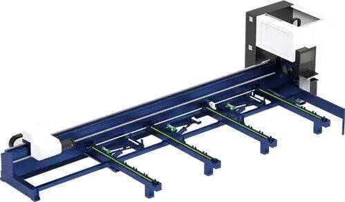
Cantilever Welding Robot solution
-


GF laser cutting machine
-

P3015 plasma cutting machine
-

LFP3015 Fiber Laser Cutter
-

pipe plasma cutting machine
-
LFH 4020 Fiber Laser Cutting Machine
-
LFP4020
-

gantry plasma air cutting machine
-

3D robot cutting machine
-

8 axis plasma cutting machine
-

5 axis plasma cutting machine
-

LT360 tube laser cutting machine
-

robot welding workstation
-

SF6060 fiber laser cutting machine
