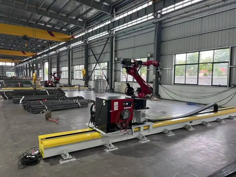
Intelligent Robotic Welder with Magnetic Crawler for Pressure Vessels

In this article
Strategic Transition to Magnetic Crawler Robotic Welding
In the field of pressure vessel fabrication, the shift from manual localized welding to autonomous systems is driven by the demand for volumetric integrity and metallurgical consistency. The integration of an Intelligent Robotic Welder equipped with a magnetic crawler addresses the primary limitation of traditional automation: the fixed track system. By utilizing high-flux permanent magnets, these crawlers adhere directly to the ferromagnetic hull of the vessel, allowing the welding head to navigate longitudinal and circumferential seams without the time-consuming installation of external rails.
The primary process employed in this configuration is Metal Active Gas (MAG) welding. Unlike manual operations where the welder must contend with heat exhaustion and ergonomic strain, the robotic crawler maintains a constant torch angle and standoff distance. This precision is critical when working with heavy-wall thicknesses common in ASME Section VIII applications, where multiple passes are required to fill the groove. The intelligent system uses sensors to adjust parameters in real-time, compensating for minor variations in fit-up or groove geometry.
MAG Welding Parameters and Metallurgical Optimization
Efficiency in pressure vessel welding is measured by the deposition rate and the reduction of the heat-affected zone (HAZ). MAG welding optimization relies on the synergy between the power source, the wire feeder, and the robotic controller. By utilizing pulsed-spray transfer modes, the robotic system minimizes spatter and ensures deep penetration even at higher travel speeds. Typical wire diameters of 1.2mm or 1.4mm are utilized, providing a balance between high deposition and controllable puddle dynamics.
The robotic controller manages the shielding gas flow, typically an Argon/CO2 mix, ensuring that the weld pool remains protected from atmospheric nitrogen and oxygen. Because the crawler moves at a programmed, steady rate, the heat input (kJ/mm) remains constant. This consistency prevents grain growth in the base metal, which is a frequent failure point in manual welding where travel speed often fluctuates. The result is a weld joint that consistently exceeds the minimum tensile and impact requirements of high-pressure service.
The Mechanics of Magnetic Crawler Integration
The core of the system is the mobility platform. Magnetic crawler integration allows the robot to transcend the limitations of floor-mounted gantry systems. These units utilize high-traction wheels or tracks embedded with neodymium magnets, providing sufficient pull-off force to carry the weight of the welding torch, wire feeder, and umbilical cables while maintaining a safety factor of 3:1 against slippage. This vertical or even overhead climbing capability ensures that large-diameter vessels can be welded in a single setup.
Control systems for these crawlers include high-resolution encoders and laser-based seam tracking. The laser sensor scans the weld joint millimeters ahead of the arc, feeding data back to the motion controller to adjust the crawler’s path. This “search and track” capability is vital for Pressure Vessels where slight cylindrical deviations are common. By maintaining the arc precisely at the root of the joint, the system significantly reduces the risk of lack-of-fusion (LOF) defects.
Calculating Labor ROI and Throughput Gains
From an industrial engineering perspective, the justification for robotic crawlers lies in the labor ROI. Manual welding of large vessels is characterized by low duty cycles, often as low as 20% to 30%, due to the need for frequent breaks, repositioning, and setup. A robotic crawler increases the arc-on time to 70% or higher. When analyzing the cost per pound of weld metal deposited, the robotic system drastically reduces the labor overhead.
Consider the following comparison for a standard 10-meter longitudinal seam:
| Metric | Manual Welding | Robotic Magnetic Crawler |
|---|---|---|
| Arc-On Time | 25% | 75% |
| Weld Defect Rate | 3-5% | <0.5% |
| Setup Time per Vessel | Minimal | Moderate (Programming/Calibration) |
| Net Throughput | 1x | 2.5x – 3x |
While the initial capital expenditure (CAPEX) for a magnetic crawler system is high, the payback period is typically reached within 12 to 18 months in high-volume shops. The reduction in post-weld repair costs is often the deciding factor; the cost of grinding out and re-welding a failed X-ray section in a pressure vessel can be five times the cost of the initial weld.
Maintenance Protocols for High-Availability Systems
To ensure the longevity of the robotic system, a rigorous preventive maintenance schedule is mandatory. The harsh environment of pressure vessel fabrication involves high temperatures and conductive dust, both of which can degrade electronic and mechanical components. Maintenance is divided into three categories: consumables, the crawler mechanism, and the power source.
Consumable Management
The contact tip and gas nozzle are the most frequently replaced items. In a robotic setup, an automated torch cleaning station is often integrated. Every few cycles, the crawler moves the torch to a station that reams out spatter and sprays anti-spatter fluid. This extends the life of the nozzle and ensures stable gas flow, which is critical for preventing porosity in the weld bead.
Crawler and Magnet Maintenance
The magnetic tracks must be inspected daily for the accumulation of metallic fines. If iron filings build up on the magnets, the traction force decreases, potentially leading to a catastrophic fall. Engineers must also check the integrity of the umbilical cord—the lifeline carrying power, gas, and data—as it is subject to friction against the vessel walls. Routine lubrication of the drive gears and calibration of the encoders ensure that the travel speed remains within the +/- 1% tolerance required for qualified weld procedures.
Power Source and Calibration
The inverter power source requires quarterly calibration to ensure that the voltage and amperage readouts on the robot HMI match the actual output at the arc. Any deviation can lead to out-of-spec heat input, which compromises the vessel’s certification. Internal cooling fans and filters must be cleaned to prevent thermal shutdown during high-duty cycle operations.
Future-Proofing Through Intelligent Software
Modern robotic crawlers are now being equipped with data-logging software that records every parameter of every weld. This “digital twin” of the welding process provides a permanent record for quality assurance. If a vessel fails in service, engineers can pull the specific data logs for the corresponding weld seam to verify that all parameters remained within the specified Welding Procedure Specification (WPS). This level of traceability is becoming a requirement for high-pressure and nuclear-grade vessels.
The integration of an intelligent robotic welder with a magnetic crawler represents a paradigm shift in heavy manufacturing. By combining the mobility of a crawler with the precision of MAG welding, manufacturers can achieve levels of productivity and quality that are unattainable through manual labor. The focus on maximizing arc-on time, coupled with a disciplined approach to maintenance, ensures that the investment delivers long-term value and maintains the rigorous safety standards required for pressure-retaining equipment.