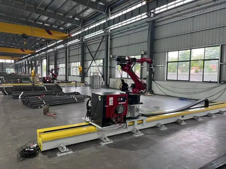
Intelligent Robotic Welder with 3D Vision positioning for Steel Structure

In this article
Integrating 3D Vision in Heavy Steel Robotic Welding
In the traditional steel structure fabrication environment, variability is the primary obstacle to automation. Unlike the automotive industry, where parts are stamped with high precision, heavy steel components—such as H-beams, box columns, and gusset plates—often exhibit significant dimensional tolerances. This is where 3D vision positioning becomes the critical enabler. By utilizing structured light or laser-profiling sensors, the robotic system can scan the actual workpiece geometry in real-time, identifying the precise location of the weld root despite variations in fit-up or thermal distortion.
The industrial engineer views this not just as a hardware upgrade, but as a systematic solution to the “teaching” bottleneck. Manual programming for every unique joint in a structural project is economically unfeasible. Intelligent vision systems allow for “point-and-shoot” or autonomous path generation, where the software compares the scanned point cloud against the CAD model to adjust the welding torch trajectory. This ensures that the robotic MAG welding process maintains consistent penetration and bead geometry, regardless of whether the joint gap is 2mm or 4mm.
MAG Welding Parameters and Process Control
Metal Active Gas (MAG) welding remains the workhorse of structural steel due to its high deposition rates and cost-effective consumables. When transitioned to a robotic platform, the process moves from a fluctuating manual operation to a controlled high-output state. The intelligent welder manages wire feed speed, voltage, and travel speed with millisecond precision. For heavy-gauge steel, multi-pass welding is often required. The 3D vision system facilitates this by calculating the volume of the groove after each pass, adjusting the subsequent bead placement to prevent overfill or undercutting.
Gas shielding composition, typically an Argon and CO2 mix, must be optimized for the robot’s increased travel speeds. Because the robot does not suffer from fatigue, it can maintain an optimal torch angle and contact-tip-to-work distance (CTWD) throughout long seams. This stability reduces spatter and minimizes the need for post-weld grinding, which is a significant hidden cost in manual fabrication shops. The goal is a high-quality metallurgical bond that meets or exceeds AWS D1.1 standards for structural welding.
Quantifying Labor ROI and Throughput Efficiency
The primary driver for adopting Intelligent Robotic Welders is the diminishing supply of skilled structural welders and the escalating cost of manual labor. An industrial ROI analysis typically compares the “arc-on” time. A manual welder in a steel shop might achieve a duty cycle of 20% to 30%, accounting for breaks, setup, and position changes. In contrast, a robotic cell often operates at a 70% to 85% duty cycle. This leap in productivity means a single robotic station can often replace three to four manual welding stations in terms of linear meters welded per shift.
Labor ROI is also realized through the “de-skilling” of the operation. While a highly skilled welder is needed to supervise the cell and handle complex non-linear joints, the bulk of repetitive structural seams can be managed by lower-level operators trained in robotic interface management. This allows the master welders to focus on high-value tasks, quality control, and troubleshooting, effectively leveraging their expertise across a larger volume of output. When calculating the payback period, engineers must include the reduction in rework costs—robotic systems provide a consistency that manual welding cannot replicate, drastically lowering the rejection rate during ultrasonic or radiographic testing.
Maintenance Protocols for High-Availability Robotics
To sustain the ROI of an automated welding cell, a rigorous preventative maintenance (PM) schedule is mandatory. Unlike manual machines, robotic systems are integrated assemblies where a failure in one component halts the entire production line. Maintenance focus areas include:
Torch and Consumable Management
The contact tip is the most frequent point of failure. In high-duty cycle MAG welding, heat causes tip erosion, which shifts the Tool Center Point (TCP). Automated TCP calibration stations should be used every few hours to ensure the robot’s “eye” (the vision system) and “hand” (the torch) remain perfectly synchronized. Additionally, the wire liner must be replaced periodically to prevent friction-induced feed fluctuations that lead to arc instability.
3D Vision Sensor Calibration
The 3D vision sensor is exposed to harsh ultraviolet light, heat, and weld spatter. Protective clear lenses or “sacrificial windows” are essential. Maintenance staff must ensure these windows are cleaned or replaced regularly. A clouded sensor leads to “noise” in the point cloud, resulting in seam tracking errors. High-end systems utilize air knives to blow debris away from the sensor face during the welding process, but manual inspection remains a daily requirement.
Wire Delivery and Drive Rolls
For large steel structures, robots often use bulk wire drums (250kg to 500kg). The wire delivery conduit must be kept clean to prevent “bird-nesting” at the drive rolls. Drive roll tension must be calibrated to the specific wire diameter and material hardness to ensure slip-free feeding without deforming the wire, which can cause erratic arc behavior and premature tip wear.
The Industrial Impact on Structural Fabrication
The implementation of steel structure automation through intelligent welding is a strategic shift toward data-driven manufacturing. By collecting data on every weld—voltage, current, gas flow, and travel speed—fabricators can provide digital twins of the structural integrity of a building or bridge. This level of traceability is becoming a requirement for high-stakes infrastructure projects.
Furthermore, the ergonomic benefits cannot be overstated. Welding heavy steel involves working in awkward positions, exposure to fumes, and extreme heat. Moving the operator from the weld puddle to a control console improves safety and long-term health, which indirectly contributes to ROI by reducing workers’ compensation claims and turnover. The 3D vision system acts as the bridge between the digital design and the physical reality, ensuring that the final steel assembly matches the engineering intent with sub-millimeter precision.
Technical Conclusion and Strategy
Deploying an intelligent robotic welder for Steel Structures is an exercise in precision engineering. It requires a synergy between 3D vision sensing, MAG process control, and disciplined maintenance. For the industrial engineer, the objective is clear: maximize the arc-on time while minimizing the variability of the output. As vision algorithms become more robust and integration costs decrease, the transition from manual to robotic welding is no longer an optional upgrade but a necessity for remaining competitive in the global structural steel market. The focus must remain on the weld seam tracking capabilities and the long-term reliability of the system to ensure that the initial capital expenditure translates into sustainable operational profit.