The Engineering Shift to Automated H-Beam Processing
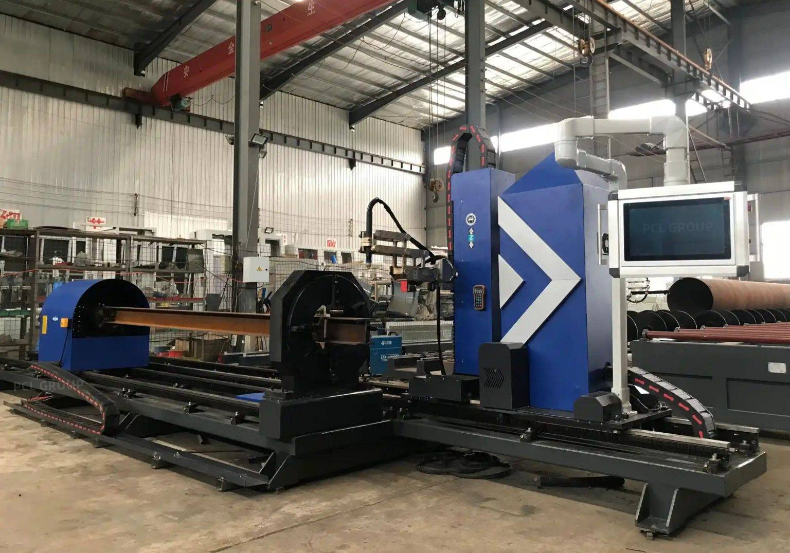
In contemporary structural steel fabrication, the H-Beam Production Line has evolved from manual marking and mechanical sawing to integrated robotic plasma cells. This transition is driven by the need for higher throughput and the elimination of human error during the layout phase. An industrial engineer views the H-beam not merely as a static component, but as a complex geometric challenge requiring precise intersections and preparation for structural loading. The core of this efficiency lies in the synergy between high-definition plasma power sources and sophisticated motion control systems.
Traditional methods often resulted in bottlenecks at the fitting station due to dimensional variances. By implementing plasma technology coupled with 3D scanning or probing, fabricators can account for material deformations such as camber and sweep, which are inherent in hot-rolled steel. The objective is to achieve a “bolt-ready” or “weld-ready” part directly from the cutting cell, minimizing secondary handling and grinding operations.
Achieving High-Level Intersection Accuracy
One of the most significant challenges in structural steel is the execution of complex intersections, such as “fish-mouth” cuts, coping, and flange thinnings. Plasma Cutting accuracy is dictated by the ability of the system to maintain a constant standoff distance and torch angle relative to the material surface. In an automated H-beam line, a multi-axis robotic arm or a specialized gantry system maneuvers the plasma torch around the web and flanges.
Coordinate Transformation and Kerf Compensation
To ensure intersection accuracy, the control system must perform real-time coordinate transformations. The software must calculate the kerf—the width of the material removed by the plasma arc—and adjust the tool path accordingly. Unlike simple 2D cutting, H-beam processing requires 3D kerf compensation, especially when the torch is tilted for beveling. Industrial-grade plasma systems utilize advanced gas flow regulation and stable arc voltage sensing to ensure the cut edge remains perpendicular or at the precise specified angle, preventing gaps that compromise structural integrity during assembly.
Mitigating Thermal Distortion
While plasma is a thermal process, modern high-definition units concentrate the energy into a narrower arc. This reduces the Heat Affected Zone (HAZ) and minimizes thermal distortion of the H-beam. By optimizing the cutting sequence—starting with the web and moving to the flanges—engineers can manage the heat distribution across the profile, ensuring that the final dimensions remain within the strict tolerances required by AISC and Eurocode standards.
Advanced Beveling for Pre-Weld Preparation
The ability to perform structural steel beveling in a single pass is a primary advantage of plasma-based H-beam lines. For heavy-duty structures, V, Y, X, and K-style bevels are essential for full penetration welds. Manually grinding these bevels is labor-intensive and prone to inconsistency. An automated plasma system can execute multi-angle bevels with high repeatability.
Robotic Articulation and Torch Kinematics
A 6-axis or 7-axis robotic configuration allows the torch to access the “inner” side of the H-beam flanges, a task that is geometrically restricted for standard 3-axis machines. The offline programming software generates the kinematics required to maintain the focal point of the plasma arc at the intersection of the material planes. This ensures that the root face of the bevel is consistent throughout the length of the cut, which is critical for the subsequent fit-up process.
Low Maintenance and Industrial Durability
From a maintenance engineering perspective, plasma systems are favored in heavy industrial environments for their robustness. Unlike technologies that require ultra-clean environments or sensitive optical alignments, plasma cutting is resilient to the dust, vibration, and temperature fluctuations common in steel service centers. The primary wear items are limited to consumables—nozzles, electrodes, and swirl rings—which can be replaced in minutes without specialized tools.
Optimized Consumable Life
Modern plasma power supplies feature “LongLife” technology, which manages the ramp-up and ramp-down of gas and current to reduce electrode wear. By monitoring the number of pierces and total arc-on time through the control interface, maintenance teams can perform predictive replacements, avoiding unplanned downtime. Furthermore, the lack of complex mechanical transmission components—such as the heavy-duty blades found in bandsaws—significantly reduces the lubrication and alignment requirements of the production line.
The Critical Role of Offline Programming (OLP)
The efficiency of an H-beam line is often limited not by the speed of the torch, but by the speed of data preparation. Offline programming (OLP) allows engineers to generate cutting paths and G-code in a virtual environment while the machine is actively processing another beam. This eliminates “machine-side” programming and ensures that the spindle or torch utilization rate remains above 85%.
Integration with BIM and CAD/CAM
OLP software acts as the bridge between Building Information Modeling (BIM) data—usually from platforms like Tekla Structures or SDS2—and the robotic controller. The software imports the 3D model, identifies the H-beam profile, and automatically assigns the optimal cutting parameters based on material thickness and grade. This digital thread ensures that every hole, notch, and bevel matches the master design exactly.
Simulation and Collision Avoidance
Before the code is sent to the floor, OLP software runs a full kinematic simulation. This identifies potential collisions between the torch head and the beam flanges or the machine’s own support structure. For H-beams, where the torch often operates in tight spaces between flanges, this simulation is vital for preventing expensive hardware damage. It also allows for the optimization of lead-ins and lead-outs, ensuring that the plasma arc stabilizes before entering the critical cut path.
Conclusion: Operational Excellence in Steel Fabrication
The integration of high-definition plasma cutting with Offline Programming represents the pinnacle of current H-beam processing technology. By focusing on the precision of intersections and the repeatability of complex bevels, fabricators can significantly reduce the “cost per ton” of structural steel. The low-maintenance nature of plasma systems ensures high uptime, while the OLP workflow removes the data bottlenecks that historically plagued manual shops. For the industrial engineer, this combination delivers a measurable increase in quality, safety, and throughput, positioning the production line for the demands of modern infrastructure projects.
-


Cantilever Welding Robot solution
-


GF laser cutting machine
-

P3015 plasma cutting machine
-

LFP3015 Fiber Laser Cutter
-

pipe plasma cutting machine
-
LFH 4020 Fiber Laser Cutting Machine
-
LFP4020
-

gantry plasma air cutting machine
-

3D robot cutting machine
-

8 axis plasma cutting machine
-

5 axis plasma cutting machine
-

LT360 tube laser cutting machine
-

robot welding workstation
-

SF6060 fiber laser cutting machine
Advanced Fiber Laser Tube Processing Technology
Our CNC Fiber Laser Tube Cutting systems revolutionize metal fabrication by integrating high-precision cutting, punching, and profiling into a single automated workflow. Designed for versatility, this technology handles a wide array of profiles including Round, Square, Rectangular, and Oval tubes, as well as complex L-shaped and U-shaped channels.
- Precision Punching: High-speed hole punching with micron-level accuracy, eliminating the need for mechanical drilling or die-stamping.
- Complex Profiling: Advanced 3D pathing allows for intricate interlocking joints and specialized notch cuts, ideal for structural frames.
- High Material Efficiency: Intelligent nesting software minimizes scrap, reducing raw material costs across large production runs.
- Clean Finish: Delivers oxide-free, burr-free edges that require zero secondary grinding before welding.

Seamlessly processing multiple profiles with consistent precision.
Global Delivery & Logistics



From our high-tech manufacturing facility directly to your global site. PCL WeldCut ensures secure packaging, professional handling, and reliable international logistics to safeguard your equipment throughout the entire journey.