Optimizing H-Beam Production for LNG Infrastructure
Liquefied Natural Gas (LNG) projects represent some of the most demanding environments for structural steel fabrication. The integrity of pipe racks, module frames, and support structures hinges on the precision of H-beam components. In this industrial context, the H-Beam Production Line has evolved from manual layout and mechanical cutting to fully integrated offline programming systems paired with multi-axis Plasma Cutting robots. This transition is driven by the need for extreme dimensional accuracy and the ability to handle complex geometries without interrupting the physical production flow.
The Role of Offline Programming in Complex Steel Fabrication
Offline Programming (OLP) serves as the digital brain of the modern production line. In LNG projects, structural designs are typically managed in 3D BIM environments like Tekla Structures or SDS/2. OLP allows engineers to import these complex models directly into the fabrication software. By simulating the plasma torch path in a virtual environment, engineers can identify potential collisions and optimize cutting sequences before a single piece of steel is loaded onto the conveyor.
This approach eliminates the “trial and error” phase on the shop floor. For H-beams used in LNG modules, where beam sizes vary significantly across a single rack, OLP ensures that every cope, block-out, and bolt hole is positioned with sub-millimeter precision. The software automatically accounts for the plasma kerf width, ensuring that the final physical dimensions match the digital twin precisely.
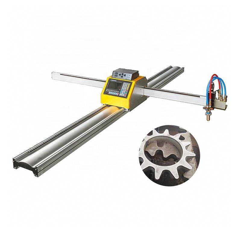
Plasma Cutting Precision and Intersection Accuracy
The primary challenge in H-beam fabrication for LNG Projects is the complexity of intersections. Beams often require intricate coping to accommodate intersecting pipes, bracing, and secondary steel members. Intersection accuracy is not merely an aesthetic requirement; it is a structural necessity. Improperly fitted joints create gaps that lead to uneven stress distribution and require excessive filler material during subsequent assembly stages.
Robotic Plasma Path Calibration
Modern H-beam lines utilize six-axis robotic arms equipped with high-definition plasma torches. Unlike traditional three-axis machines, these systems can navigate the inner surfaces of the flanges and the web simultaneously. The OLP software generates a tool path that maintains a constant standoff distance between the plasma nozzle and the steel surface, even when navigating the radius of the beam’s inner fillet. This constant distance is crucial for maintaining arc stability and ensuring a clean, square cut across the entire cross-section of the H-beam.
Managing Thermal Distortion
Plasma cutting involves intense localized heat. However, modern high-speed plasma systems minimize the Heat Affected Zone (HAZ) by optimizing travel speeds. In LNG applications, where material properties must remain consistent to handle cryogenic temperature shifts, maintaining the metallurgical integrity of the H-beam is paramount. Through precise OLP-controlled speed adjustments, the plasma system ensures that thermal input is kept to a minimum, preventing the warping or twisting of long-span H-beams.
Advanced Beveling for High-Strength Connections
LNG structural modules are subjected to immense static and dynamic loads. Consequently, most structural connections require full-thickness preparation. Plasma cutting beveling technology allows for the simultaneous cutting and chamfering of H-beam ends. Instead of a secondary process involving manual grinding or oxy-fuel beveling, the robotic plasma torch performs V, Y, X, and K-style bevels in a single pass.
Automated Beveling Consistency
Manual beveling is prone to human error, often resulting in inconsistent root faces or improper angles. In a production line integrated with OLP, the bevel parameters are pulled directly from the structural design files. The robot adjusts its tilt and rotation in real-time to create a uniform bevel along the web and flanges. This consistency is vital for the automated assembly processes that follow, ensuring that fit-up tolerances are met every time.
Optimizing Weld Preparation Geometry
In LNG pipe racks, H-beams often meet at oblique angles. Traditional cutting methods struggle with these three-dimensional geometries. Plasma systems, guided by OLP, can execute “rat holes” (weld access holes) and complex miter cuts with integrated bevels. This eliminates hours of manual rework and ensures that the structural integrity of the joint is optimized for the specific load-bearing requirements of the LNG facility.
H-Beam Production Efficiency and Low Maintenance Requirements
From an industrial engineering perspective, the Total Cost of Ownership (TCO) of a production line is as important as its output speed. Plasma cutting systems are favored in heavy H-beam lines due to their low maintenance profile and high uptime. Unlike other thermal cutting technologies that require delicate optics or high-pressure gas seals, plasma power sources are designed for the rugged, dusty environments of a steel fabrication shop.
Durability of Plasma Components
The consumable parts in a plasma torch—nozzles, electrodes, and swirl rings—are designed for quick replacement. Modern systems feature “plug-and-play” torch heads that can be swapped in minutes. This is critical for LNG projects with tight commissioning deadlines where any downtime on the main H-beam line can delay the entire module assembly sequence. Furthermore, the absence of complex beam-delivery systems reduces the need for specialized technicians and frequent recalibration.
Reliability in High-Volume Environments
Plasma power sources are solid-state and air-cooled or liquid-cooled, making them resilient to temperature fluctuations within the factory. In an LNG-focused production line, where beams can weigh several tons and cause significant vibration when moved, the robust nature of plasma hardware ensures that the precision of the cut is not compromised by the mechanical realities of heavy material handling.
Data Integration and Workflow Optimization
The synergy between OLP and plasma cutting extends to data management. Every beam processed in the line is tracked via its unique ID, often linked to a barcode or QR code. The OLP software records the cutting parameters, time per part, and consumable wear. This data is invaluable for project managers overseeing massive LNG contracts, as it allows for accurate forecasting of production timelines and material costs.
Reducing Material Waste through Nesting
While H-beams are linear members, OLP nesting algorithms can optimize the placement of cuts across standard mill lengths to minimize “off-cuts” or scrap. In the context of expensive, high-grade structural steel required for LNG projects, a 3% to 5% reduction in material waste can result in significant cost savings. The plasma system’s ability to perform common-cut sequences—where one cut serves as the end of one component and the start of the next—further enhances this efficiency.
Streamlining Post-Cutting Operations
By achieving high-precision cuts and perfect bevels at the start of the production chain, the subsequent stages of assembly are greatly simplified. Components arrive at the fit-up stations ready for immediate placement. The accuracy provided by the OLP-plasma combination ensures that the final dimensions of the LNG modules stay within the tight tolerances required for site installation, where hundreds of modules must align perfectly on the foundation bolts.
Conclusion: The Future of LNG Steel Fabrication
The integration of high-definition plasma cutting with sophisticated H-beam production line offline programming represents the pinnacle of current structural steel fabrication. For the LNG sector, this technological stack provides the necessary precision for complex intersections, the safety assurance of automated beveling, and the economic benefit of a low-maintenance, high-uptime system. As LNG projects continue to grow in scale and complexity, the reliance on these automated, data-driven fabrication methods will only increase, cementing plasma cutting’s role as the workhorse of heavy structural engineering.
-


Cantilever Welding Robot solution
-


GF laser cutting machine
-

P3015 plasma cutting machine
-

LFP3015 Fiber Laser Cutter
-

pipe plasma cutting machine
-
LFH 4020 Fiber Laser Cutting Machine
-
LFP4020
-

gantry plasma air cutting machine
-

3D robot cutting machine
-

8 axis plasma cutting machine
-

5 axis plasma cutting machine
-

LT360 tube laser cutting machine
-

robot welding workstation
-

SF6060 fiber laser cutting machine
Advanced Fiber Laser Tube Processing Technology
Our CNC Fiber Laser Tube Cutting systems revolutionize metal fabrication by integrating high-precision cutting, punching, and profiling into a single automated workflow. Designed for versatility, this technology handles a wide array of profiles including Round, Square, Rectangular, and Oval tubes, as well as complex L-shaped and U-shaped channels.
- Precision Punching: High-speed hole punching with micron-level accuracy, eliminating the need for mechanical drilling or die-stamping.
- Complex Profiling: Advanced 3D pathing allows for intricate interlocking joints and specialized notch cuts, ideal for structural frames.
- High Material Efficiency: Intelligent nesting software minimizes scrap, reducing raw material costs across large production runs.
- Clean Finish: Delivers oxide-free, burr-free edges that require zero secondary grinding before welding.

Seamlessly processing multiple profiles with consistent precision.
Global Delivery & Logistics



From our high-tech manufacturing facility directly to your global site. PCL WeldCut ensures secure packaging, professional handling, and reliable international logistics to safeguard your equipment throughout the entire journey.