Technical Foundations of H-Beam Processing for Pressure Vessels
In the realm of heavy industrial fabrication, specifically for the oil, gas, and power generation sectors, the structural integration of H-beams with pressure vessels demands a level of precision that transcends standard construction requirements. The production line must be optimized not just for throughput, but for the exacting tolerances required by Narrow Gap Welding protocols. Unlike traditional welding methods, narrow gap preparations require significantly less filler material and provide a reduced heat-affected zone (HAZ), yet they are unforgiving regarding fit-up gaps.
The initial stage of this production cycle hinges on the Plasma Cutting station. In a specialized H-beam line, the plasma system is tasked with transforming raw structural steel into a refined component ready for robotic welding. This process involves intricate 3D geometry where the H-beam must often be contoured to meet the cylindrical or spherical surface of a pressure vessel. Any deviation in the cutting path results in excessive gaps that can compromise the integrity of the narrow gap weld, leading to potential failure under high-pressure cycles.
High-Definition Plasma and Intersection Accuracy
The core of the cutting station is the CNC-controlled plasma gantry, often equipped with a multi-axis rotatable head. Intersection Accuracy is the primary metric of performance here. When an H-beam intersects a vessel wall at an angle, the resulting cut profile is a complex saddle curve. Achieving this with manual layout or basic 2D cutting is impossible within the tolerances required for automated welding.
High-definition plasma systems utilize sophisticated software algorithms to calculate the torch path in real-time. This accounts for the thickness of the beam flanges and the web, adjusting the torch angle dynamically to ensure the cut face remains perpendicular or at a specific bevel relative to the vessel’s surface. This precision ensures that the root opening remains consistent across the entire joint. For pressure vessels, where radiographic testing (RT) and ultrasonic testing (UT) are standard, a tight fit-up facilitated by plasma precision is the first line of defense against weld defects such as lack of fusion or slag inclusion.
Kinematics and Path Planning
The kinematics of the plasma head involve simultaneous movement across five or six axes. As the torch traverses the H-beam, it must compensate for the beam’s own structural variances—such as slight twists or flange misalignments—which are common in hot-rolled sections. Probing systems and laser sensors are often integrated into the plasma station to map the actual profile of the beam before the arc is struck. This data is fed back into the CNC, allowing for “kerf compensation” and path correction, ensuring that the finished part matches the digital twin precisely.
Plasma Beveling for Narrow Gap Preparation
The shift toward narrow gap techniques is driven by the need for efficiency in thick-walled vessel fabrication. Traditional wide-angle V-grooves require multiple weld passes and high volumes of consumable wire. In contrast, Plasma Beveling allows for the creation of steep-angle grooves, often between 5 and 7 degrees, with a small root face.
The plasma torch must maintain a consistent arc voltage to ensure the bevel angle is uniform throughout the cut. Fluctuations in the distance between the nozzle and the workpiece can result in “bevel deviation,” which is unacceptable for narrow gap configurations. Modern H-beam lines employ automated Torch Height Control (THC) systems that respond in milliseconds to surface irregularities. By producing a clean, oxide-free bevel surface, the plasma system reduces the need for secondary grinding, allowing the beam to move directly from the cutting station to the welding gantry.
Edge Quality and Metallurgical Integrity
For pressure vessels, the quality of the cut edge is paramount. Plasma cutting, particularly when using high-definition oxygen or nitrogen-shielded processes, produces a very narrow HAZ. This is critical because an oversized HAZ can alter the grain structure of the steel, potentially leading to hydrogen-induced cracking or reduced toughness in the joint. By optimizing the cutting speed and gas flow, the H-Beam Production Line ensures that the mechanical properties of the S355 or high-tensile alloy steel remain within the design specifications of the pressure vessel code (such as ASME Section VIII).
H-Beam Low Maintenance and System Uptime
Industrial engineers prioritize reliability in production line design. One of the standout features of integrated plasma systems is H-beam Low Maintenance requirements compared to mechanical cutting or older thermal methods. A plasma system lacks the complex blade-wear issues of saws or the high-sensitivity optics of other thermal processes that struggle in the dusty, vibration-heavy environment of a structural steel shop.
Consumable Longevity and Diagnostics
The maintenance profile of a modern plasma station is centered on predictable consumable replacement. Electrodes, nozzles, and swirl rings are designed for high duty cycles. Integrated diagnostic systems monitor the arc stability and gas pressure, alerting operators before a consumable failure affects the cut quality. This predictive maintenance approach is essential for maintaining the continuous flow of an H-beam production line.
Furthermore, the robust nature of the plasma power source allows it to operate in non-climate-controlled environments common in heavy fabrication. The absence of complex beam-delivery systems (like those found in older laser technologies) means there are fewer points of failure. The gantry and rails, while requiring periodic lubrication and alignment checks, are built to withstand the impact of loading and unloading heavy H-beams weighing several tons.
Integration with CNC Control Systems
The synergy between the plasma station and the overall production management system is what defines a modern industrial facility. CNC Control Systems today do more than just move the torch; they manage the nesting of parts, track heat numbers for material traceability (a requirement for pressure vessels), and log the parameters of every cut.
This digital integration ensures that the “as-built” geometry of the H-beam is recorded. If a specific weld fails inspection, the engineer can trace the data back to the cutting parameters to determine if a geometric deviation or a thermal anomaly was the root cause. This level of data transparency is vital for QA/QC protocols in high-stakes industries like nuclear power or offshore chemical processing.
Optimizing the Workflow for Pressure Vessel Supports
In practice, the H-beam production line functions as a high-speed preparation center. Once the H-beam is loaded onto the conveyor, the system identifies the profile, probes for alignment, and executes the intersection cuts and narrow gap bevels in a single sequence. The beam is then ready for the next phase: integration with the vessel body. By eliminating manual marking, hand-cutting, and heavy grinding, the plasma-centric line reduces the labor hours per ton significantly while simultaneously increasing the safety factor of the final product.
Summary of Engineering Advantages
The strategic implementation of high-definition plasma cutting within an H-beam production line provides the precision necessary for the demanding requirements of pressure vessel fabrication. Through superior intersection accuracy and the ability to produce tight-tolerance narrow gap bevels, these systems ensure that structural components meet rigorous safety standards. The inherent low maintenance of the hardware combined with advanced CNC control makes it the optimal choice for industrial engineers seeking to balance high throughput with the uncompromising quality required for high-pressure applications.
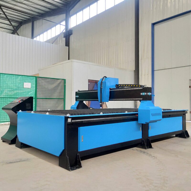
-


Cantilever Welding Robot solution
-


GF laser cutting machine
-

P3015 plasma cutting machine
-

LFP3015 Fiber Laser Cutter
-

pipe plasma cutting machine
-
LFH 4020 Fiber Laser Cutting Machine
-
LFP4020
-

gantry plasma air cutting machine
-

3D robot cutting machine
-

8 axis plasma cutting machine
-

5 axis plasma cutting machine
-

LT360 tube laser cutting machine
-

robot welding workstation
-

SF6060 fiber laser cutting machine
Advanced Fiber Laser Tube Processing Technology
Our CNC Fiber Laser Tube Cutting systems revolutionize metal fabrication by integrating high-precision cutting, punching, and profiling into a single automated workflow. Designed for versatility, this technology handles a wide array of profiles including Round, Square, Rectangular, and Oval tubes, as well as complex L-shaped and U-shaped channels.
- Precision Punching: High-speed hole punching with micron-level accuracy, eliminating the need for mechanical drilling or die-stamping.
- Complex Profiling: Advanced 3D pathing allows for intricate interlocking joints and specialized notch cuts, ideal for structural frames.
- High Material Efficiency: Intelligent nesting software minimizes scrap, reducing raw material costs across large production runs.
- Clean Finish: Delivers oxide-free, burr-free edges that require zero secondary grinding before welding.

Seamlessly processing multiple profiles with consistent precision.
Global Delivery & Logistics



From our high-tech manufacturing facility directly to your global site. PCL WeldCut ensures secure packaging, professional handling, and reliable international logistics to safeguard your equipment throughout the entire journey.