Optimizing H-Beam Production for Pressure Vessel Integration
In the heavy industrial sector, specifically within pressure vessel manufacturing, the structural integrity of support frames and internal reinforcements relies heavily on the precision of H-beam components. The transition toward advanced welding techniques has placed a higher demand on the initial cutting phase. Implementing a specialized Plasma Cutting Intersection Accuracy protocol ensures that structural members interface with cylindrical shells with minimal gap variance. This precision is foundational for the subsequent narrow gap welding processes which require exacting tolerances to ensure deep penetration and structural homogeneity.
The Critical Role of Plasma Intersection Accuracy
Pressure vessels often require H-beams to be contoured to fit the radius of a tank or to intersect other structural members at non-orthogonal angles. Traditional mechanical cutting methods fail to provide the necessary three-dimensional geometry required for these intersections. High-definition plasma systems, integrated into the H-Beam Production Line, utilize multi-axis torch heads to execute complex saddle cuts and miter joints.
The engineering objective is to achieve a fit-up tolerance of less than 1.0mm across the entire intersection profile. When the plasma system compensates for the kerf and the beam’s flange-to-web thickness variations in real-time, the resulting component requires no manual trimming. This level of accuracy is essential because narrow gap welding cannot accommodate the wide or inconsistent root openings often found in lower-quality thermal cutting operations. By maintaining a tight intersection, the heat input during welding is more controlled, reducing the risk of localized deformation in the pressure vessel shell.
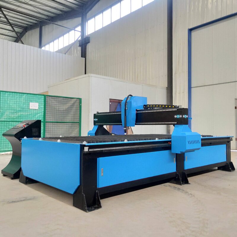
Narrow Gap Welding Preparation and Beveling Requirements
Narrow gap welding (NGW) is the preferred method for thick-walled pressure vessels due to its ability to reduce the volume of weld metal deposited, thereby decreasing cycle times and material costs. However, NGW is highly sensitive to groove geometry. The plasma cutting station must perform Narrow Gap Welding Preparation by creating steep bevel angles, typically between 1 and 7 degrees, depending on the material thickness and the specific welding procedure specification (WPS).
Advanced Beveling Capabilities of Plasma Systems
Modern H-beam lines utilize plasma torches mounted on robotic or CNC-controlled rotators to provide Automated Beveling Cycles. Unlike standard straight cuts, these bevels must remain consistent across the flanges and the web of the H-beam. Industrial engineers prioritize plasma for this task because it can maintain a stable arc at the steep angles required for narrow gap grooves. The process eliminates the metallurgical “smearing” often seen with mechanical beveling tools, providing a clean, oxide-free surface when the correct shielding gas mixtures, such as Argon-Hydrogen blends, are employed for stainless steel or high-alloy components.
Consistency in Groove Geometry
The repeatability of the plasma arc ensures that every H-beam processed on the line is identical. In a pressure vessel assembly, where multiple support beams must align perfectly to distribute load across a saddle or skirt, this consistency is vital. The plasma system’s software integrates directly with TEKLA or CAD/CAM models, translating the structural design into precise torch paths that account for the thermal expansion of the beam during the cutting process. This proactive thermal management ensures that the final dimensions of the groove remain within the strict margins required for automated welding tractors.
H-Beam Production Efficiency: The Low Maintenance Advantage
From an operational standpoint, the Total Cost of Ownership (TCO) of a production line is heavily influenced by maintenance schedules and downtime. In the context of Heavy-Duty H-Beam Processing, plasma systems offer a robust solution that thrives in the dusty, high-vibration environments characteristic of heavy fabrication shops. Unlike more sensitive optical cutting technologies, plasma systems are comprised of durable mechanical components that are resistant to the scale and surface contaminants common on hot-rolled H-beams.
Consumable Life and System Uptime
The engineering of modern plasma torches has significantly extended the life of electrodes and nozzles. Rapid-fire ignition systems and liquid-cooled torch bodies allow for high duty cycles, which is critical when processing several hundred meters of H-beam per shift. The “low maintenance” aspect of plasma stems from the simplicity of its core components. The power supply, gas console, and torch leads are designed for field serviceability. In an H-beam line, where the cutting station is the primary bottleneck, the ability to perform a 60-second consumable change-out ensures that the downstream welding stations remain fed with material.
Resistance to Industrial Contaminants
H-beams used in pressure vessel frames are often stored outdoors and may develop surface rust or mill scale. Plasma cutting is inherently tolerant of these surface conditions. The high-energy plasma stream penetrates through contaminants without the risk of “back-reflection” or lens damage. This makes it the most reliable choice for structural steel fabrication where pre-cleaning every beam to a mirror finish is economically unfeasible. By reducing the sensitivity of the cutting process, the facility maintains a higher Overall Equipment Effectiveness (OEE).
Integration of Plasma Cutting into the Automated Workflow
The modern H-beam production line is an ecosystem where the plasma station acts as the primary data-capture point. As the beam enters the cutting cell, laser sensors or mechanical probes measure the actual dimensions of the beam—detecting any camber, sweep, or flange tilt. The plasma system’s CNC then adjusts the cutting path to ensure that the intersection geometry is correct relative to the beam’s actual shape, rather than its theoretical CAD model.
Streamlining Post-Cutting Logistics
Because the plasma system delivers a weld-ready finish, the H-beam can move directly from the cutting bed to the assembly jig. The elimination of a secondary grinding or edge-cleaning station reduces the footprint of the production line and lowers labor costs. for Pressure Vessels, where weld quality is subject to radiographic testing (RT) or ultrasonic testing (UT), the clean edge provided by plasma cutting reduces the likelihood of slag inclusions or lack of fusion at the root of the narrow gap weld.
Safety and Environmental Considerations
The integration of high-efficiency dust collection and water tables within the plasma cutting section of the H-beam line ensures that the working environment remains compliant with industrial health and safety standards. Effective smoke extraction at the point of the cut prevents the accumulation of metallic dust, which can interfere with the electronic components of the automated welding systems further down the line. This holistic approach to system design further reinforces the reliability of the plasma cutting stage in a high-output manufacturing environment.
Summary of Technical Benefits for Pressure Vessel Structural Components
In summary, the selection of plasma cutting for H-beam production lines dedicated to pressure vessel fabrication is a strategic decision based on three technical pillars: intersection precision, specialized beveling for narrow gap welding, and operational robustness. By focusing on these areas, industrial engineers can ensure that the structural foundation of the vessel meets all regulatory and safety codes while maintaining a highly efficient, low-maintenance production flow. The ability to produce complex, weld-ready geometries in a single pass remains the most effective way to optimize the fabrication of heavy-duty structural members.
-


Cantilever Welding Robot solution
-


GF laser cutting machine
-

P3015 plasma cutting machine
-

LFP3015 Fiber Laser Cutter
-

pipe plasma cutting machine
-
LFH 4020 Fiber Laser Cutting Machine
-
LFP4020
-

gantry plasma air cutting machine
-

3D robot cutting machine
-

8 axis plasma cutting machine
-

5 axis plasma cutting machine
-

LT360 tube laser cutting machine
-

robot welding workstation
-

SF6060 fiber laser cutting machine
Advanced Fiber Laser Tube Processing Technology
Our CNC Fiber Laser Tube Cutting systems revolutionize metal fabrication by integrating high-precision cutting, punching, and profiling into a single automated workflow. Designed for versatility, this technology handles a wide array of profiles including Round, Square, Rectangular, and Oval tubes, as well as complex L-shaped and U-shaped channels.
- Precision Punching: High-speed hole punching with micron-level accuracy, eliminating the need for mechanical drilling or die-stamping.
- Complex Profiling: Advanced 3D pathing allows for intricate interlocking joints and specialized notch cuts, ideal for structural frames.
- High Material Efficiency: Intelligent nesting software minimizes scrap, reducing raw material costs across large production runs.
- Clean Finish: Delivers oxide-free, burr-free edges that require zero secondary grinding before welding.

Seamlessly processing multiple profiles with consistent precision.
Global Delivery & Logistics



From our high-tech manufacturing facility directly to your global site. PCL WeldCut ensures secure packaging, professional handling, and reliable international logistics to safeguard your equipment throughout the entire journey.