Optimizing H-Beam Production for Pressure Vessel Support
In the heavy fabrication industry, particularly for the production of pressure vessels, the structural integrity of support frames and H-beams is non-negotiable. The manufacturing process has evolved from manual layout and mechanical cutting to highly integrated thermal processing lines. Central to this evolution is the implementation of Plasma Cutting technology, which serves as the primary stage for material preparation. Unlike traditional methods, modern plasma systems provide the high-speed throughput and metallurgical quality necessary to feed subsequent stages, specifically those utilizing narrow gap welding techniques.
Pressure vessels operate under extreme thermal and barometric stress, necessitating support structures that are perfectly aligned. The H-Beam Production Line must therefore operate with a level of precision that eliminates cumulative error. By focusing on the thermal stability of the plasma arc and the mechanical rigidity of the gantry system, engineers can ensure that every flange and web component meets stringent H-Beam Structural Integrity standards before they ever reach the welding station.
Plasma Cutting and Intersection Accuracy
The intersection of H-beam components—where the web meets the flange or where the beam joins the vessel shell—is the most critical point for stress distribution. Achieving high intersection accuracy requires a plasma system with superior motion control. Industrial-grade plasma torches are now mounted on multi-axis robotic arms or high-precision gantries that utilize real-time feedback loops to correct for material warping or slight variations in plate thickness.
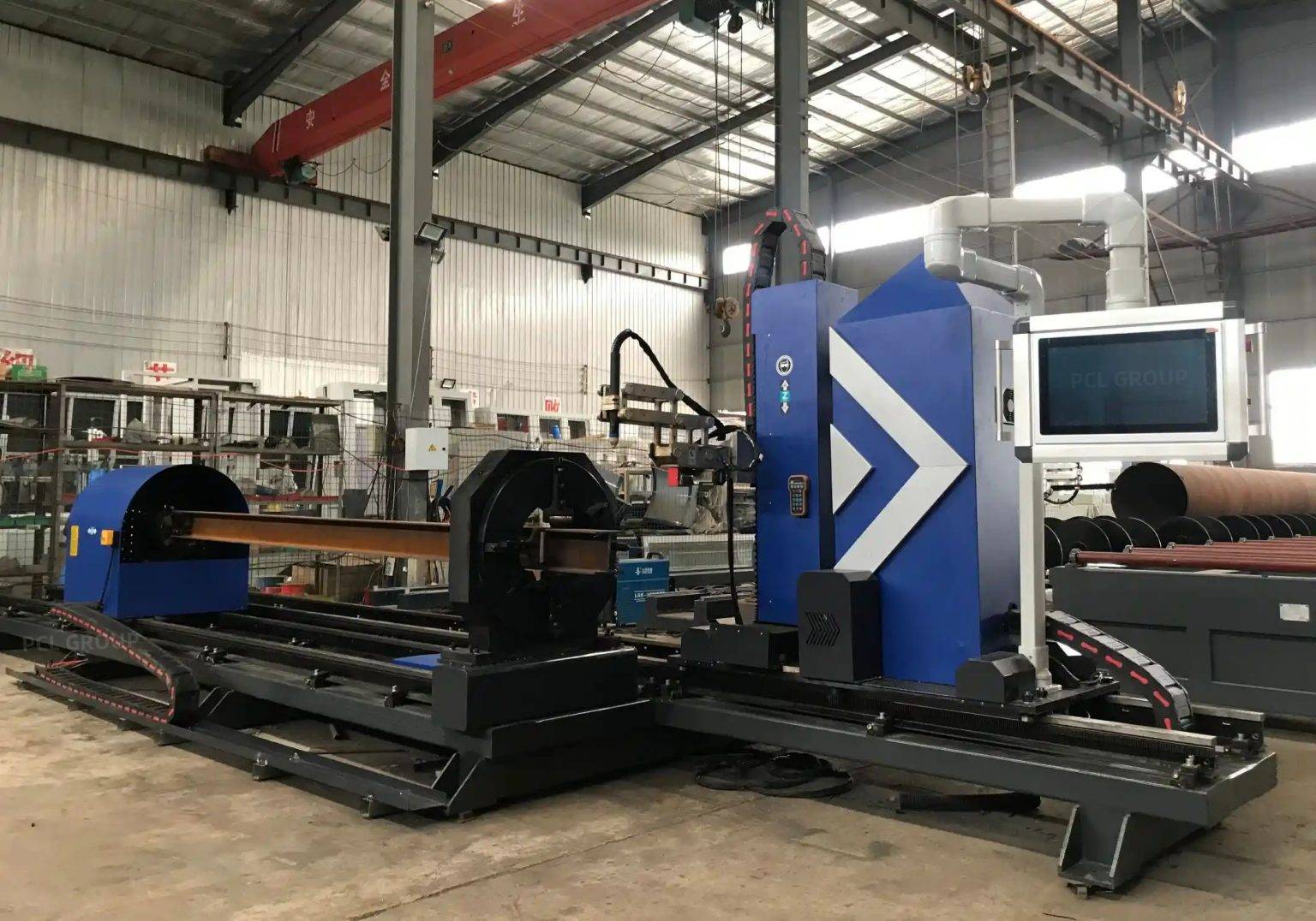
Intersection accuracy in this context refers to the tight tolerances required for fit-up. When preparing H-beams for narrow gap welding, the gap between components must be consistent within fractions of a millimeter. Plasma cutting achieves this through high-definition arc technology, which constricts the plasma gas to increase energy density. This results in a narrower kerf and a significantly reduced heat-affected zone (HAZ), ensuring that the geometric dimensions of the beam remain stable during the cooling phase. For pressure vessel applications, where the beam must often be contoured to match the curvature of the vessel body, this level of Plasma Arc Precision is essential for avoiding structural voids or excessive filler metal consumption.
Advanced Beveling for Narrow Gap Preparation
Narrow gap welding requires specific edge geometries to allow the welding torch to reach the root of the joint without excessive oscillation. Plasma cutting systems integrated into H-beam lines are equipped with 3D beveling heads capable of executing V, Y, X, and K cuts in a single pass. This capability is vital for Narrow Gap Welding Preparation, as it allows for the creation of steep bevel angles (often between 5 to 20 degrees) that are difficult to achieve with mechanical milling on large structural sections.
The ability to bevel the edges of H-beam flanges with plasma technology reduces the total volume of the weld groove. In the context of pressure vessels, this translates to fewer welding passes and a lower overall heat input into the base metal, which preserves the mechanical properties of the steel. The plasma system’s software calculates the necessary offsets for the bevel angle, ensuring that the effective throat of the weld will meet the design specifications dictated by ASME or similar regulatory bodies. By automating this process, the production line eliminates the variability of manual grinding, resulting in a uniform surface finish that is conducive to high-quality ultrasonic testing (UT) results.
Low Maintenance and Operational Continuity
One of the primary drivers for selecting plasma technology in an H-beam production line is the low maintenance requirement compared to mechanical or older thermal alternatives. Modern plasma power supplies are designed with long-life consumable sets. Electrodes and nozzles are engineered with advanced cooling channels and hafnium inserts that can withstand thousands of starts before requiring replacement. This longevity is critical in a high-volume production environment where downtime directly impacts the bottom line.
Furthermore, the “low maintenance” aspect extends to the dross management and slag removal systems. High-definition plasma systems produce a virtually dross-free cut on H-beam materials, reducing the need for secondary cleaning operations. The integration of automated slag conveyors and dust extraction systems ensures that the internal components of the H-beam line remain free from conductive metallic dust, which is a common cause of electrical failure in industrial environments. By reducing the frequency of intervention, engineers can maintain a higher duty cycle, ensuring that the Automated Beveling Cycles are not interrupted by frequent part changes or system calibrations.
Technical Integration of Thermal Processing Software
The efficiency of a plasma-based H-beam line is largely dependent on the software architecture that drives the hardware. Industrial engineers utilize nesting and CAD/CAM software to optimize material usage and define the precise cutting paths for complex intersections. In pressure vessel support fabrication, this software must handle the “unfolding” of curved intersections where the beam meets the vessel’s cylindrical or spherical shell.
The software also manages the compensation for the plasma arc’s natural taper. Even high-definition systems have a slight taper, and the control system must adjust the torch angle dynamically to ensure that the vertical edges of the H-beam flanges are perfectly square where they will be joined. This digital twin approach—where the cutting path is simulated and optimized before the first arc is struck—guarantees that the intersection accuracy is maintained across hundreds of identical components, providing the consistency required for automated narrow gap welding systems to follow.
Efficiency Metrics and Quality Control
From an industrial engineering perspective, the performance of the plasma cutting stage is measured by its “First Time Yield” (FTY). In H-beam production for Pressure Vessels, an FTY of 98% or higher is targeted. This is achieved through the synergy of robust mechanical design and precision thermal delivery. The plasma system must be capable of maintaining its accuracy even as the ambient temperature in the facility fluctuates, which requires a frame with high thermal mass and vibration damping characteristics.
Quality control is integrated directly into the cutting cycle. Many advanced lines now feature laser scanning heads that verify the dimensions of the cut part immediately after the plasma torch has completed its path. If a flange width or a bevel angle deviates from the programmed tolerance, the system can alert the operator or make real-time adjustments to subsequent cuts. This proactive approach to quality ensures that every H-beam delivered to the narrow gap welding station is a “perfect fit,” minimizing the risk of weld defects such as lack of fusion or slag inclusions which are costly to repair in pressure vessel components.
Conclusion on Plasma Implementation
The implementation of high-precision plasma cutting within an H-beam production line represents a strategic investment in accuracy and reliability. By focusing on the nuances of intersection geometry and the specific requirements of narrow gap welding preparation, manufacturers can significantly enhance their throughput while maintaining the rigorous safety standards of the pressure vessel industry. The combination of low maintenance requirements and high-speed thermal processing ensures that plasma remains the superior choice for heavy structural fabrication, providing the foundational precision upon which all subsequent welding and assembly stages depend.
-


LT240S tube laser cutting machine
-
LT120S tube laser cutting machine
-
Sale

Tank Fillet Welding Machine
Original price was: $1,000.00.$900.00Current price is: $900.00. -
Sale

MAK100 tube laser cutting machine
Original price was: $5,500.00.$5,000.00Current price is: $5,000.00. -

portable plasma air cutting machine
$1,200.00 -

2in1 fiber laser cutting machine
-

Air cooling Laser welding machine
-

HF h beam laser cutting machine
-

LT240 laser cutting machine
-

Laser welding machine
-


Cobot Welding Station
-

Gantry welding robot solution
-

Tracked Wheeled AGV Welding robot
-

LFH6020 Fiber laser cutting machine
-
LFP6020
-

robotic welidng machine
Advanced Fiber Laser Tube Processing Technology
Our CNC Fiber Laser Tube Cutting systems revolutionize metal fabrication by integrating high-precision cutting, punching, and profiling into a single automated workflow. Designed for versatility, this technology handles a wide array of profiles including Round, Square, Rectangular, and Oval tubes, as well as complex L-shaped and U-shaped channels.
- Precision Punching: High-speed hole punching with micron-level accuracy, eliminating the need for mechanical drilling or die-stamping.
- Complex Profiling: Advanced 3D pathing allows for intricate interlocking joints and specialized notch cuts, ideal for structural frames.
- High Material Efficiency: Intelligent nesting software minimizes scrap, reducing raw material costs across large production runs.
- Clean Finish: Delivers oxide-free, burr-free edges that require zero secondary grinding before welding.

Seamlessly processing multiple profiles with consistent precision.
Global Delivery & Logistics



From our high-tech manufacturing facility directly to your global site. PCL WeldCut ensures secure packaging, professional handling, and reliable international logistics to safeguard your equipment throughout the entire journey.