Optimizing H-Beam Production for Oil and Gas Structural Requirements
In the fabrication of large-scale storage tanks and offshore structural frameworks, the H-beam serves as a primary load-bearing element. The transition toward automated production lines has highlighted the necessity for precision at the earliest stages of the manufacturing workflow. For Oil and Gas applications, where structural integrity is non-negotiable, the synergy between the cutting process and subsequent welding phases determines the lifecycle of the asset. Specifically, the adoption of narrow gap welding preparation demands a level of accuracy that traditional mechanical cutting or manual thermal processes cannot consistently provide.
The industrial shift focuses on leveraging Plasma Cutting systems to handle high-tensile carbon steels and alloys. Unlike lighter industrial applications, Oil and Gas components often involve significant flange thicknesses and web depths. The ability to maintain a consistent kerf and precise torch angle over long production runs is the cornerstone of a high-performance H-beam line.
The Role of Plasma Intersection Accuracy in Fit-Up Quality
One of the most complex aspects of H-beam fabrication is the management of intersections—where the web meets the flange or where beams intersect in a complex lattice for tank supports. Plasma intersection accuracy is a critical metric because it directly impacts the volume of filler metal required during the welding stage. In a narrow gap configuration, the tolerance for gap fluctuation is minimal. If the intersection is not cut with geometric precision, the automated welding head will encounter variations that lead to lack of fusion or excessive penetration.
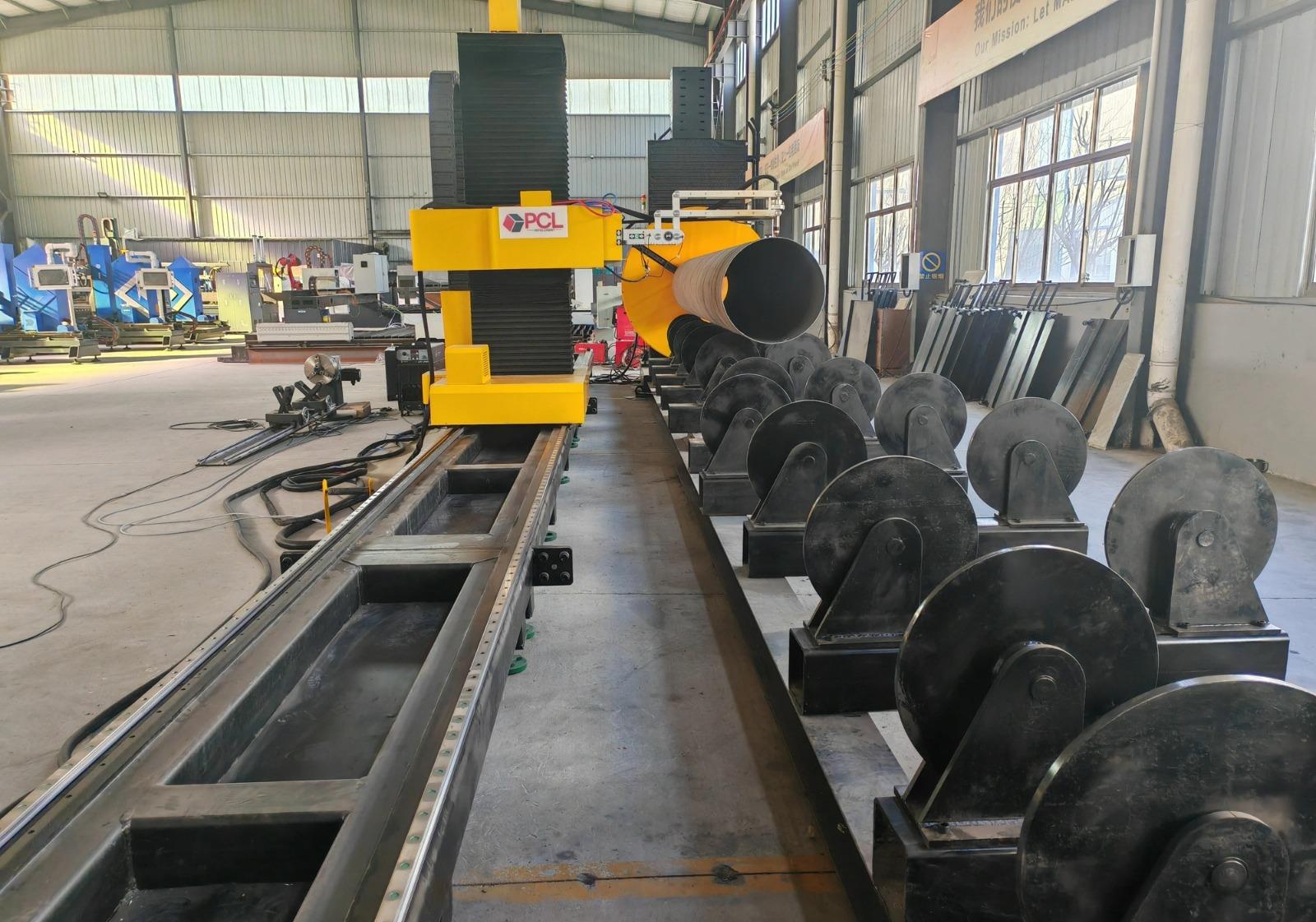
Geometric Tolerances and Thermal Management
Modern plasma systems integrated into H-beam lines utilize multi-axis robotic heads or CNC gantries that compensate for the natural bevel of the plasma arc. By employing real-time sensing and compensation algorithms, the system ensures that the root face of the cut remains perfectly perpendicular or at the exact specified angle. This precision reduces the need for secondary grinding, which is often a bottleneck in heavy fabrication environments. By maintaining tight tolerances at the intersection, the structural engineer ensures that the load distribution across the beam remains consistent with the original design parameters.
Automated Beveling for Narrow Gap Welding Preparation
Narrow gap welding is preferred in the Oil and Gas industry for its ability to reduce the total heat input and minimize the volume of weld metal in thick-walled sections. However, this technique is entirely dependent on the quality of the bevel. High-definition plasma cutting systems enable automated beveling cycles that can produce V, Y, or J-groove geometries in a single pass.
Consistency in Groove Geometry
For H-beams used in tank wall reinforcements, the bevel must be uniform across the entire length of the component. Any deviation in the bevel angle or the root land thickness can cause instabilities in the narrow gap arc. Plasma technology, specifically when paired with high-current power sources, allows for a stable arc that maintains constant energy density. This stability results in a smooth surface finish on the cut face, which is essential for preventing inclusions and ensuring the integrity of the ultrasonic testing (UT) or radiographic testing (RT) required by industry standards like API 650.
Reducing Heat Affected Zones (HAZ)
While all thermal cutting processes create a heat-affected zone, modern high-speed plasma systems minimize this area by increasing the travel speed and concentrating the energy. For the metallurgical requirements of Oil and Gas steels, maintaining the grain structure near the fusion line is vital. Precise plasma parameters ensure that the HAZ is shallow enough to be consumed by the subsequent narrow gap welding pass, resulting in a homogenous transition between the base metal and the weld deposit.
H-Beam Low Maintenance and Operational Continuity
In a continuous production environment, downtime is the primary enemy of profitability. One of the significant advantages of plasma systems in an H-beam line is the H-beam low maintenance profile of the cutting equipment. Unlike mechanical saws that require constant blade sharpening and replacement, or waterjet systems that demand complex abrasive management, plasma systems rely on a relatively simple consumable set consisting of electrodes, nozzles, and shields.
Consumable Lifecycle Management
Advancements in torch design have led to long-life consumables that can withstand the high duty cycles common in heavy-duty fabrication. Integrated software now tracks the number of pierces and the total arc-on time, providing predictive maintenance alerts before the cut quality begins to degrade. This allows maintenance teams to schedule consumable changes during natural breaks in production, rather than responding to unplanned failures that could ruin an expensive H-beam section.
Robustness in Harsh Industrial Environments
Oil and Gas fabrication facilities are often demanding environments with airborne particulates and temperature fluctuations. Plasma cutting systems are inherently robust, with few moving parts exposed to the cutting zone compared to other technologies. The torch leads and internal components are shielded from the high-temperature sparks and slag generated during the cutting of heavy flanges. This durability ensures that the production line remains operational for multiple shifts with minimal intervention, contributing to a lower total cost of ownership (TCO).
Integrating Cutting Precision with Downstream Narrow Gap Processes
The ultimate goal of focusing on plasma cutting precision is to facilitate a seamless transition to the welding station. In a narrow gap setup, the welding torch operates within a confined space, often with only a few millimeters of clearance on either side. If the H-beam has been cut with high intersection accuracy and a perfect bevel, the welding automation can maintain a constant arc length and travel speed.
Improving Throughput via Precision
When the plasma system delivers a part that is “weld-ready” directly from the cutting bed, the entire throughput of the facility increases. Eliminating the need for manual fit-up adjustments or corrective grinding means that the welding station can achieve a higher duty cycle. In the context of Oil and Gas tanks, where kilometers of welding may be required for a single project, the cumulative time savings of precise plasma cutting are substantial.
Technical Conclusion for Industrial Planning
Industrial engineers designing H-Beam Production Lines for the energy sector must prioritize the cutting stage as the foundation of the entire process. By selecting plasma systems capable of high intersection accuracy and specialized beveling, they ensure that the narrow gap welding process—the most time-consuming and quality-sensitive part of the build—is supported by perfect geometry. Furthermore, the low maintenance requirements of plasma technology provide the operational reliability needed to meet the tight delivery schedules typical of global Oil and Gas projects. The investment in high-definition plasma cutting is not merely an investment in a tool, but an investment in the structural integrity and efficiency of the entire fabrication workflow.
-


Cantilever Welding Robot solution
-


GF laser cutting machine
-

P3015 plasma cutting machine
-

LFP3015 Fiber Laser Cutter
-

pipe plasma cutting machine
-
LFH 4020 Fiber Laser Cutting Machine
-
LFP4020
-

gantry plasma air cutting machine
-

3D robot cutting machine
-

8 axis plasma cutting machine
-

5 axis plasma cutting machine
-

LT360 tube laser cutting machine
-

robot welding workstation
-

SF6060 fiber laser cutting machine
Advanced Fiber Laser Tube Processing Technology
Our CNC Fiber Laser Tube Cutting systems revolutionize metal fabrication by integrating high-precision cutting, punching, and profiling into a single automated workflow. Designed for versatility, this technology handles a wide array of profiles including Round, Square, Rectangular, and Oval tubes, as well as complex L-shaped and U-shaped channels.
- Precision Punching: High-speed hole punching with micron-level accuracy, eliminating the need for mechanical drilling or die-stamping.
- Complex Profiling: Advanced 3D pathing allows for intricate interlocking joints and specialized notch cuts, ideal for structural frames.
- High Material Efficiency: Intelligent nesting software minimizes scrap, reducing raw material costs across large production runs.
- Clean Finish: Delivers oxide-free, burr-free edges that require zero secondary grinding before welding.

Seamlessly processing multiple profiles with consistent precision.
Global Delivery & Logistics



From our high-tech manufacturing facility directly to your global site. PCL WeldCut ensures secure packaging, professional handling, and reliable international logistics to safeguard your equipment throughout the entire journey.