Optimization of H-Beam Production for LNG Infrastructure
The global surge in Liquefied Natural Gas (LNG) processing and transport infrastructure demands structural components capable of withstanding extreme thermal cycles and mechanical stress. Central to this fabrication requirement is the heavy-duty H-beam, often utilized in modular pipe racks and terminal frameworks. To meet the stringent standards of the energy sector, industrial engineers are increasingly prioritizing Plasma Cutting Systems as the primary method for material preparation. This choice is driven by the need for high-speed processing of thick-walled sections and the preparation of complex joints necessary for subsequent Narrow Gap Welding (NGW) processes.
High-Definition Plasma Cutting and Intersection Accuracy
In the context of LNG project fabrication, the geometric precision of H-beam intersections is non-negotiable. Intersection Accuracy refers to the ability of the cutting system to maintain dimensional tolerances at the points where webs and flanges meet or where secondary bracing penetrates the primary beam. High-definition plasma systems utilize sophisticated CNC algorithms to compensate for the plasma arc’s natural kerf and taper.
For H-beams, the accuracy of the “cope” or the “rat-hole” cut determines the fit-up quality. In a production line optimized for LNG, the plasma torch must execute precise 3D movements to ensure that the mating surfaces are perfectly aligned. Any deviation in the intersection profile leads to uneven gaps, which are detrimental to the Narrow Gap Welding process. By achieving tolerances within +/- 0.5mm, plasma systems eliminate the need for manual grinding and secondary fit-up adjustments, directly increasing the linear meters of beam produced per shift.
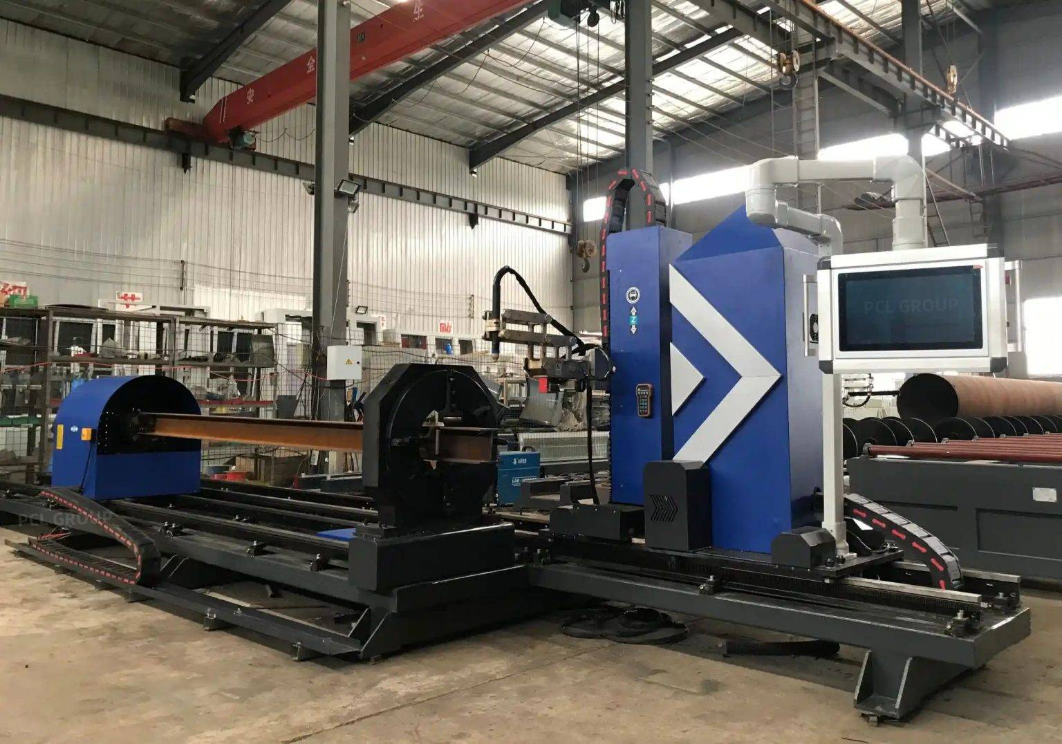
Advancements in Multi-Axis Beveling for Narrow Gap Welding
Narrow Gap Welding (NGW) is the preferred method for thick-section H-beams in LNG projects due to its ability to reduce the volume of weld metal and minimize the Heat Affected Zone (HAZ). However, the success of NGW is entirely dependent on the quality of the bevel. Narrow Gap Welding preparation requires steep bevel angles, often ranging from 3 to 7 degrees, with a high degree of consistency along the entire length of the beam section.
Modern plasma cutting units are equipped with five-axis or six-axis robotic heads that can perform V, Y, X, and K-style bevels in a single pass. This multi-axis capability allows the production line to create the complex geometries required for deep-penetration welds without moving the workpiece to a separate station. The integration of height control sensors ensures that even if the H-beam has slight material deviations or “mill-sweep,” the plasma torch maintains a constant distance, preserving the integrity of the bevel angle and the land thickness.
Low Maintenance Requirements in Heavy Industrial Environments
From an operational standpoint, the reliability of the production line is a key metric for ROI. Structural Integrity of the equipment itself is a factor, but the maintenance profile of the cutting technology is where significant cost savings are realized. Plasma systems are inherently robust and designed for the “dirty” environment of heavy steel fabrication. Unlike other high-precision methods that rely on sensitive optics or complex gas delivery systems that are prone to contamination, plasma torches are resilient.
The maintenance cycle for a high-definition plasma system is centered on consumable management—specifically the nozzle, electrode, and swirl ring. Modern systems feature “quick-change” torch designs that allow operators to replace consumables in less than two minutes, minimizing downtime. Furthermore, the absence of fragile components in the cutting head means the system can withstand the vibrations and dust common in H-beam production facilities without requiring frequent recalibration. This “up-time” advantage is critical for LNG Projects where project timelines are aggressive and liquidated damages for delays are substantial.
Thermal Management and Material Stability
One of the engineering challenges in H-beam fabrication is managing the thermal input during the cutting process to prevent distortion. While plasma is a thermal cutting process, the high speed at which it operates—especially on sections ranging from 20mm to 50mm in thickness—limits the total heat saturation of the flange or web. By optimizing the cutting sequence and using underwater or water-shrouded plasma tables, engineers can further reduce the HAZ.
This thermal stability is essential for ensuring that the H-beam retains its structural properties, particularly for steel grades designed for low-temperature service. If the cutting process introduces excessive heat, it can alter the grain structure of the steel, potentially leading to brittle fractures in cryogenic applications. The precision of the plasma arc, combined with controlled gas mixtures (such as Oxygen-Nitrogen or H35), ensures a clean, metallurgical surface ready for NGW without further chemical treatment.
Integrating Plasma Cutting into the Automated Workflow
To achieve maximum efficiency, the plasma cutting station must be digitally integrated with the downstream welding stations. Through BIM (Building Information Modeling) and TEKLA software integration, the plasma CNC can read the exact specifications of the H-beam, including all bolt holes, cope cuts, and bevel requirements. This digital twin approach ensures that the “As-Built” component matches the “As-Designed” model with zero manual data entry.
In the LNG sector, where traceability is paramount, the plasma system can also be used for automated marking. Using a low-amperage marking setting, the system can etch heat numbers, part IDs, and welding instructions directly onto the steel. This ensures that every H-beam in the production line is accounted for and that the Narrow Gap Welding parameters are correctly matched to the joint geometry prepared by the plasma torch.
Conclusion: The Engineering Rationale for Plasma in LNG Fabrication
The selection of plasma cutting technology for H-Beam Production Lines is a strategic decision based on mechanical durability and geometric precision. By focusing on the intersection accuracy required for complex modular assemblies and the exacting bevel standards of Narrow Gap Welding, industrial engineers can ensure that LNG infrastructure is built to the highest safety standards. The low maintenance overhead and high duty cycle of plasma systems provide a sustainable competitive advantage, allowing fabricators to meet the rigorous demands of the global energy market while maintaining strict control over production costs and material quality.
-


LT240S tube laser cutting machine
-
LT120S tube laser cutting machine
-
Sale

Tank Fillet Welding Machine
Original price was: $1,000.00.$900.00Current price is: $900.00. -
Sale

MAK100 tube laser cutting machine
Original price was: $5,500.00.$5,000.00Current price is: $5,000.00. -

portable plasma air cutting machine
$1,200.00 -

2in1 fiber laser cutting machine
-

Air cooling Laser welding machine
-

HF h beam laser cutting machine
-

LT240 laser cutting machine
-

Laser welding machine
-


Cobot Welding Station
-

Gantry welding robot solution
-

Tracked Wheeled AGV Welding robot
-

LFH6020 Fiber laser cutting machine
-
LFP6020
-

robotic welidng machine
Advanced Fiber Laser Tube Processing Technology
Our CNC Fiber Laser Tube Cutting systems revolutionize metal fabrication by integrating high-precision cutting, punching, and profiling into a single automated workflow. Designed for versatility, this technology handles a wide array of profiles including Round, Square, Rectangular, and Oval tubes, as well as complex L-shaped and U-shaped channels.
- Precision Punching: High-speed hole punching with micron-level accuracy, eliminating the need for mechanical drilling or die-stamping.
- Complex Profiling: Advanced 3D pathing allows for intricate interlocking joints and specialized notch cuts, ideal for structural frames.
- High Material Efficiency: Intelligent nesting software minimizes scrap, reducing raw material costs across large production runs.
- Clean Finish: Delivers oxide-free, burr-free edges that require zero secondary grinding before welding.

Seamlessly processing multiple profiles with consistent precision.
Global Delivery & Logistics



From our high-tech manufacturing facility directly to your global site. PCL WeldCut ensures secure packaging, professional handling, and reliable international logistics to safeguard your equipment throughout the entire journey.