Structural Requirements for LNG Infrastructure
Liquefied Natural Gas (LNG) projects demand structural components capable of withstanding extreme cryogenic temperatures and high mechanical loads. The H-beams utilized in these facilities, particularly for storage tank supports and process modules, must adhere to stringent metallurgical and dimensional standards. To achieve the deep penetration and high-integrity joints required, production lines are increasingly utilizing narrow gap welding techniques. However, the success of a narrow gap process is entirely dependent on the quality of the upstream preparation, specifically the precision of the plasma cutting phase.
In an industrial engineering context, the transition from standard structural fabrication to LNG-grade H-beam production involves a shift toward automated CNC plasma systems. These systems are designed to handle heavy-gauge carbon steel and specialty alloys with a focus on edge squareness and minimal thermal distortion. By eliminating manual preparation, manufacturers ensure that the subsequent welding phases proceed without the risk of volumetric defects caused by inconsistent fit-up.
Intersection Accuracy and Fit-up Precision
The primary challenge in H-beam fabrication for LNG modules is the intersection between the web and the flange. For narrow gap welding to function efficiently, the root opening must remain constant across the entire length of the beam, often exceeding 12 meters. Intersection accuracy is achieved through synchronized CNC control of the plasma head, which compensates for the natural camber and sweep of the raw material.
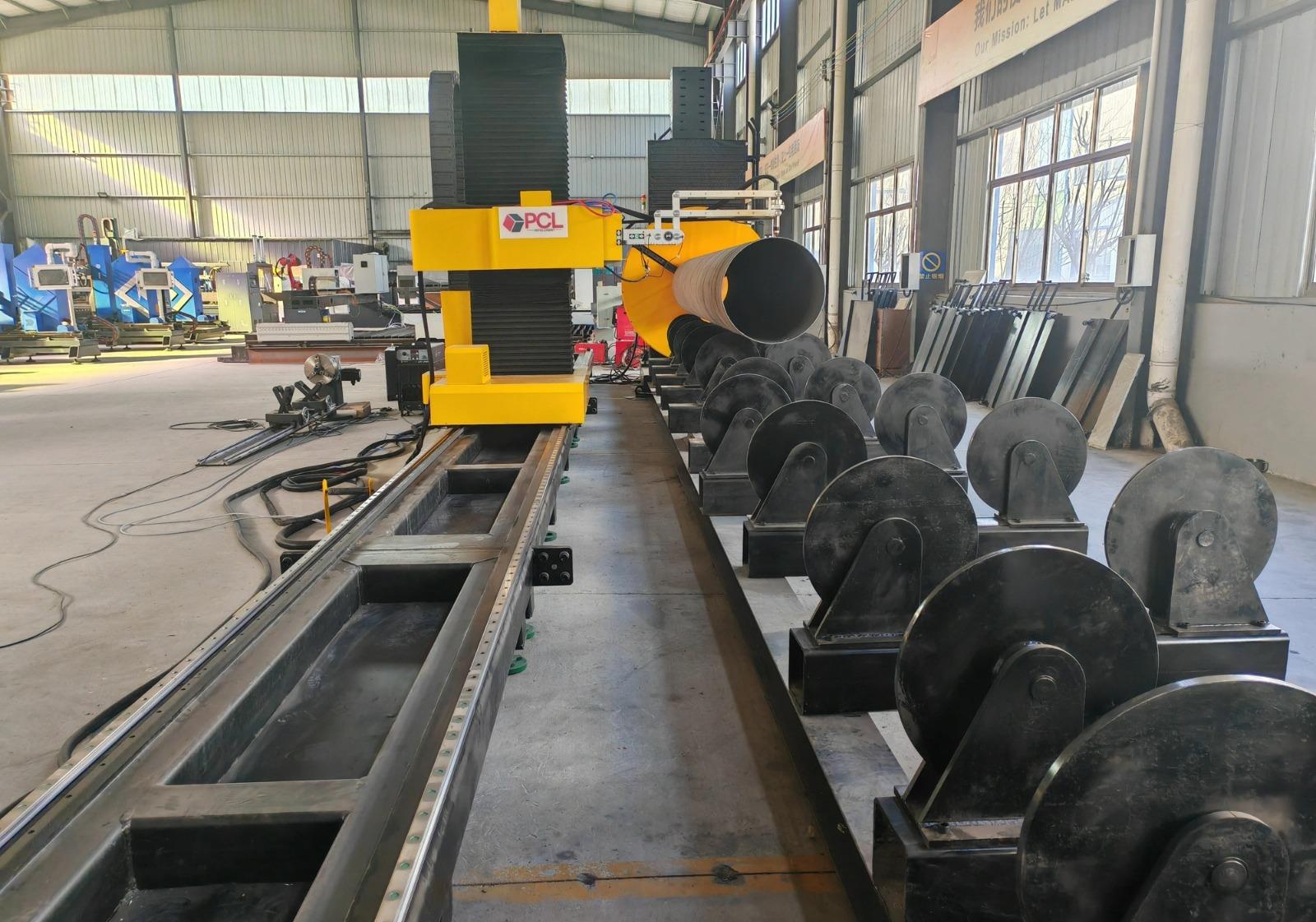
High-definition plasma systems utilize sophisticated sensing technologies, such as initial height sensing (IHS) and voltage-based torch height control (THC). These systems ensure the torch maintains a constant distance from the workpiece, regardless of plate surface irregularities. In the production of heavy H-beams, even a 1mm deviation in the web-to-flange intersection can lead to excessive weld volume or lack of fusion. By maintaining a tolerance of +/- 0.5mm, the plasma cutting station provides the geometric consistency required for automated narrow gap welding oscillators to operate without manual intervention.
Multi-Axis Plasma Beveling for Narrow Gap Prep
Narrow gap welding relies on a specific groove geometry—typically a small inclusive angle of 1 to 5 degrees—which significantly reduces the amount of filler metal required compared to standard V-grooves. Achieving this geometry on heavy H-beam sections requires multi-axis beveling capabilities. Modern plasma stations utilize a robotic or 5-axis “tilt and rotate” head that can execute complex bevel cuts on both the web and flange components simultaneously.
The engineering advantage of plasma beveling lies in its ability to produce clean, weld-ready edges on thicknesses ranging from 20mm to over 80mm. For LNG projects, where thick-walled sections are common, the plasma arc provides sufficient energy density to maintain a stable kerf even at steep angles. This process eliminates the need for secondary grinding or milling of the bevels, effectively reducing the cycle time of the production line while maintaining the integrity of the heat-affected zone (HAZ).
Thermal Management and Material Stability
Large-scale H-beam production involves significant heat input, which can introduce residual stresses and dimensional warping. Industrial engineers must optimize the cutting sequence to manage these thermal effects. By utilizing underwater plasma cutting or water-shroud technologies, the thermal footprint on the H-beam is drastically reduced. This is critical for LNG applications where the grain structure of the steel must remain stable to ensure low-temperature toughness.
The CNC software within the plasma station integrates kerf compensation algorithms that adjust the cutting path in real-time based on the thermal expansion coefficient of the material. This ensures that when the beam cools to ambient temperature, the final dimensions align perfectly with the engineering specifications. This level of predictive accuracy is what separates specialized LNG production lines from general-purpose fabrication setups.
Low Maintenance and Operational Availability
In high-volume H-beam production, downtime is the primary driver of increased overhead. H-beam low maintenance configurations for plasma systems are engineered to withstand the harsh environments of heavy fabrication shops. Unlike more delicate technologies, modern plasma torches are built with robust shielding and simplified consumable stacks that can be replaced in minutes.
Industrial-grade power supplies now feature predictive diagnostics that monitor gas flow, coolant temperature, and electrical load. By identifying wear on electrodes and nozzles before a failure occurs, maintenance teams can schedule interventions during shift changes rather than during active production. Furthermore, the absence of complex optical paths or sensitive alignment mirrors means the plasma system remains resilient against the vibrations and dust typical of structural steel environments. This reliability ensures that the production line maintains a high duty cycle, crucial for meeting the aggressive delivery schedules of global LNG infrastructure projects.
Engineering Optimization of Consumable Life
To further drive down the cost per meter of cut, engineers focus on the gas chemistry used during the plasma process. For LNG-grade steels, a mixture of Oxygen and Nitrogen or H35 (Hydrogen-Argon) can be utilized to produce dross-free cuts with minimal oxidation. Advanced gas consoles automatically adjust these mixtures based on the material thickness and cutting speed.
By optimizing the “ramp-up” and “ramp-down” of the plasma arc at the start and end of each cut, the lifespan of the copper consumables is extended by up to 30%. This systematic approach to consumable management directly impacts the ROI of the H-beam line. In a 24/7 operation, these incremental gains in component longevity result in significant annual savings and higher throughput for the narrow gap welding stations.
Integration with Downstream Narrow Gap Systems
The final stage of the plasma cutting process is the digital hand-off. The CNC coordinates used for the cut are logged and passed to the narrow gap welding controllers. This creates a “digital twin” of the beam geometry, allowing the welding robots to adjust their parameters based on the actual measured dimensions of the plasma-prepared joints.
This integration represents the pinnacle of modern H-beam production. By ensuring that the plasma cutting station provides high-precision bevels and perfect intersection accuracy, the downstream narrow gap welding process can achieve 100% radiographic success rates. For the LNG industry, where a single weld failure can lead to catastrophic consequences, this data-driven synergy between cutting and welding is the ultimate benchmark of engineering excellence.
-


Cantilever Welding Robot solution
-


GF laser cutting machine
-

P3015 plasma cutting machine
-

LFP3015 Fiber Laser Cutter
-

pipe plasma cutting machine
-
LFH 4020 Fiber Laser Cutting Machine
-
LFP4020
-

gantry plasma air cutting machine
-

3D robot cutting machine
-

8 axis plasma cutting machine
-

5 axis plasma cutting machine
-

LT360 tube laser cutting machine
-

robot welding workstation
-

SF6060 fiber laser cutting machine
Advanced Fiber Laser Tube Processing Technology
Our CNC Fiber Laser Tube Cutting systems revolutionize metal fabrication by integrating high-precision cutting, punching, and profiling into a single automated workflow. Designed for versatility, this technology handles a wide array of profiles including Round, Square, Rectangular, and Oval tubes, as well as complex L-shaped and U-shaped channels.
- Precision Punching: High-speed hole punching with micron-level accuracy, eliminating the need for mechanical drilling or die-stamping.
- Complex Profiling: Advanced 3D pathing allows for intricate interlocking joints and specialized notch cuts, ideal for structural frames.
- High Material Efficiency: Intelligent nesting software minimizes scrap, reducing raw material costs across large production runs.
- Clean Finish: Delivers oxide-free, burr-free edges that require zero secondary grinding before welding.

Seamlessly processing multiple profiles with consistent precision.
Global Delivery & Logistics



From our high-tech manufacturing facility directly to your global site. PCL WeldCut ensures secure packaging, professional handling, and reliable international logistics to safeguard your equipment throughout the entire journey.